Canopy and Rear Window - Section 38
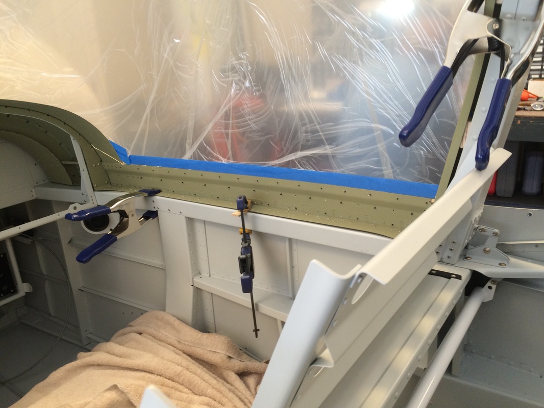
The start of fitting up the rear window. We needed to buy a # 36 & 40 Plexiglass Drill and a # 6 screw dimple die to drill and mount to the fuselage, so we are on hold until they come in from Avery
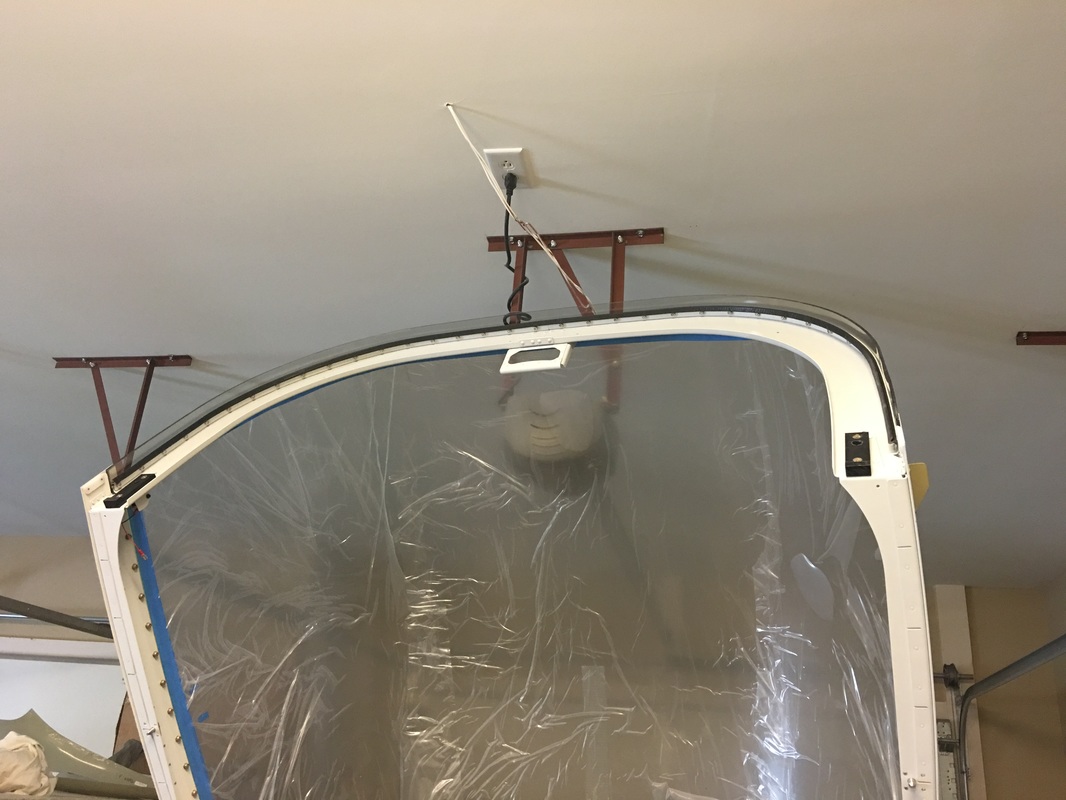
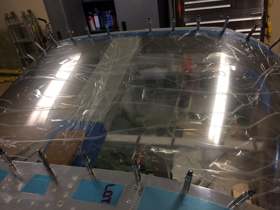
Inside view of the window, trying to ensure we have proper overlap after cutting the relief notched at the center to for the roll bar brace.
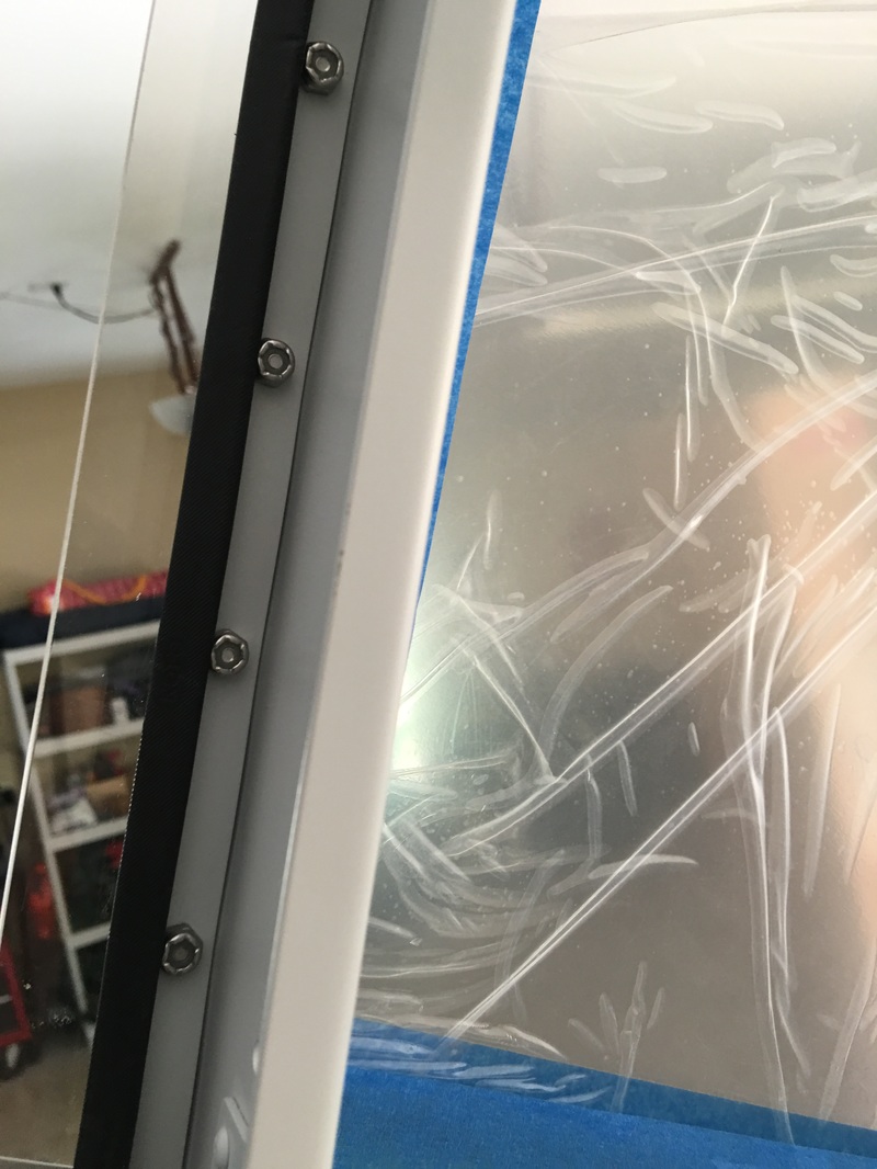
We decided to use our trusty 6 lobe stainless steel 6/32 screws on the windows. They don't corrode like the steel ones do from the moisture that is alway around the canopy glass.
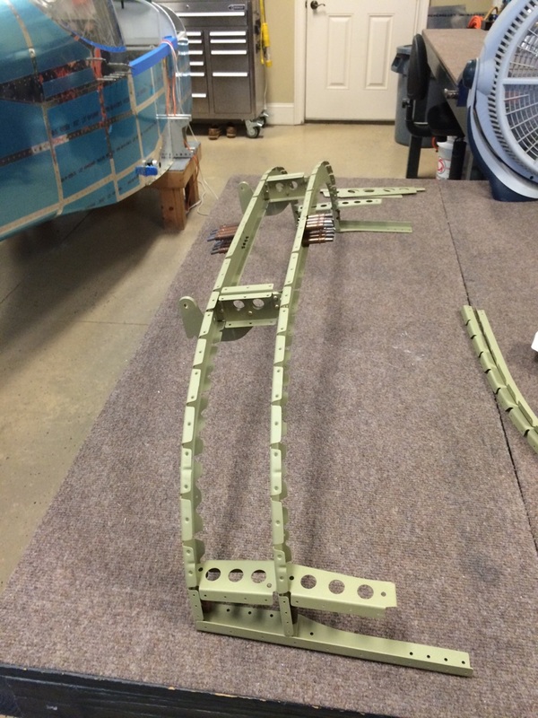
These are the canopy side frames. There some tricky fitting here, so follow the plans closely
Side view of the canopy side frames, make sure they match the fuselage sides
The fluting is critical in making these pieces and they need to me perfectly flat to fit
|
This is a view of marking where you can flute, between the rivets
|
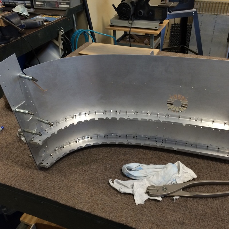
This is the area where fitting the ribs to the skin requires attention to fluting and forming the rib to lay flat to the skin, yet keeping the shape flat to the canopy rail.
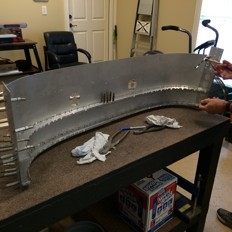
More fitting and messing to get it right
Riveting the frame and hinges together. Yikes, the front rivets on the hinge flange where tough. No room even using a crooked stick (offset rivet set) The results were fair, but not pristine.
The front hinge rivets were much easier. I was able to get the pneumatic squeezer in there with the deep throat yoke and these turned out perfect.
These rivets were squeezed, more to follow
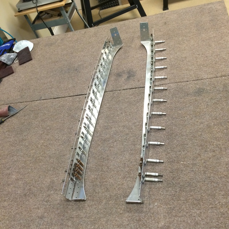
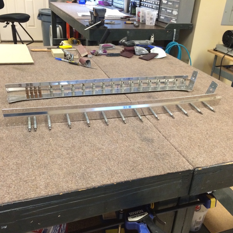
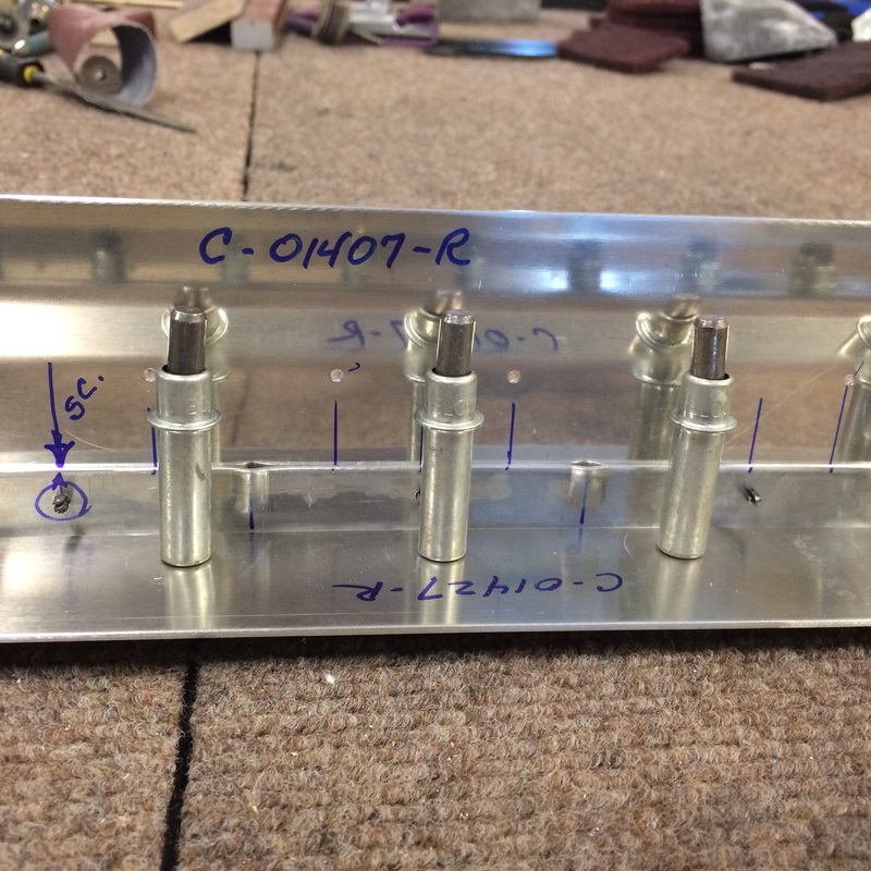
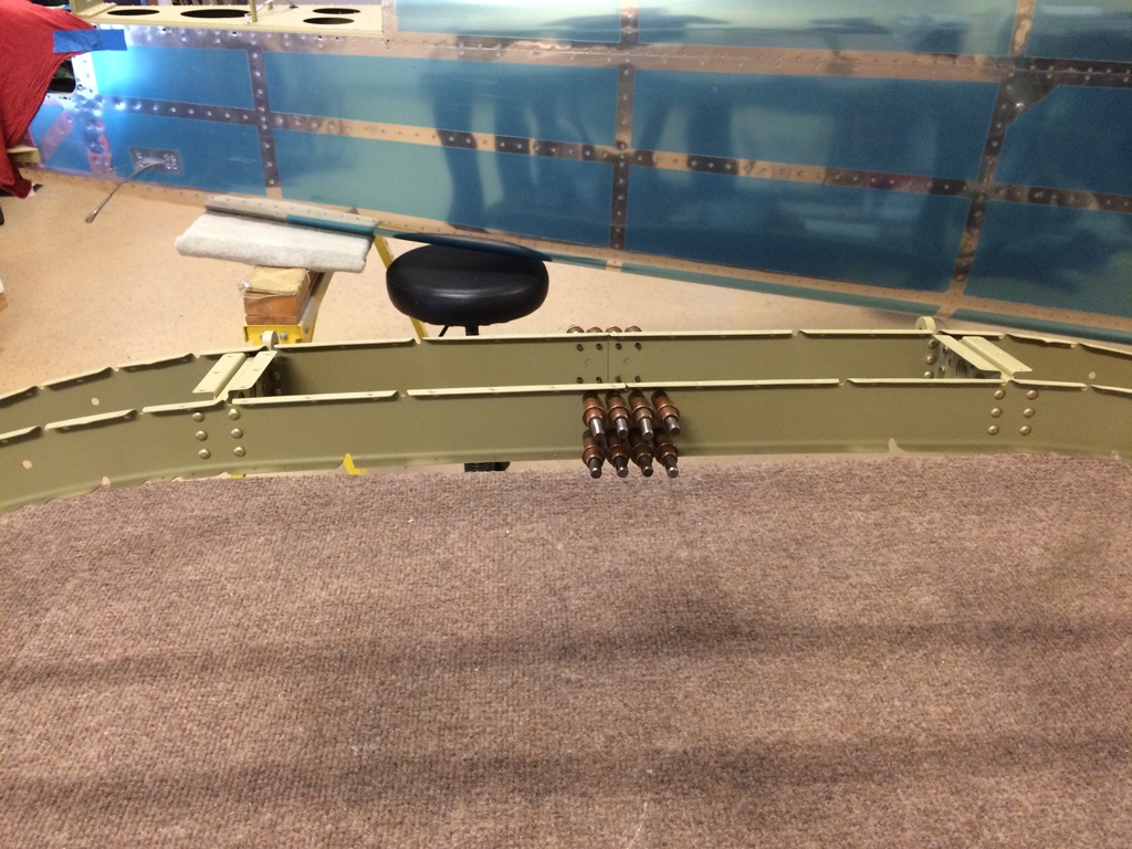
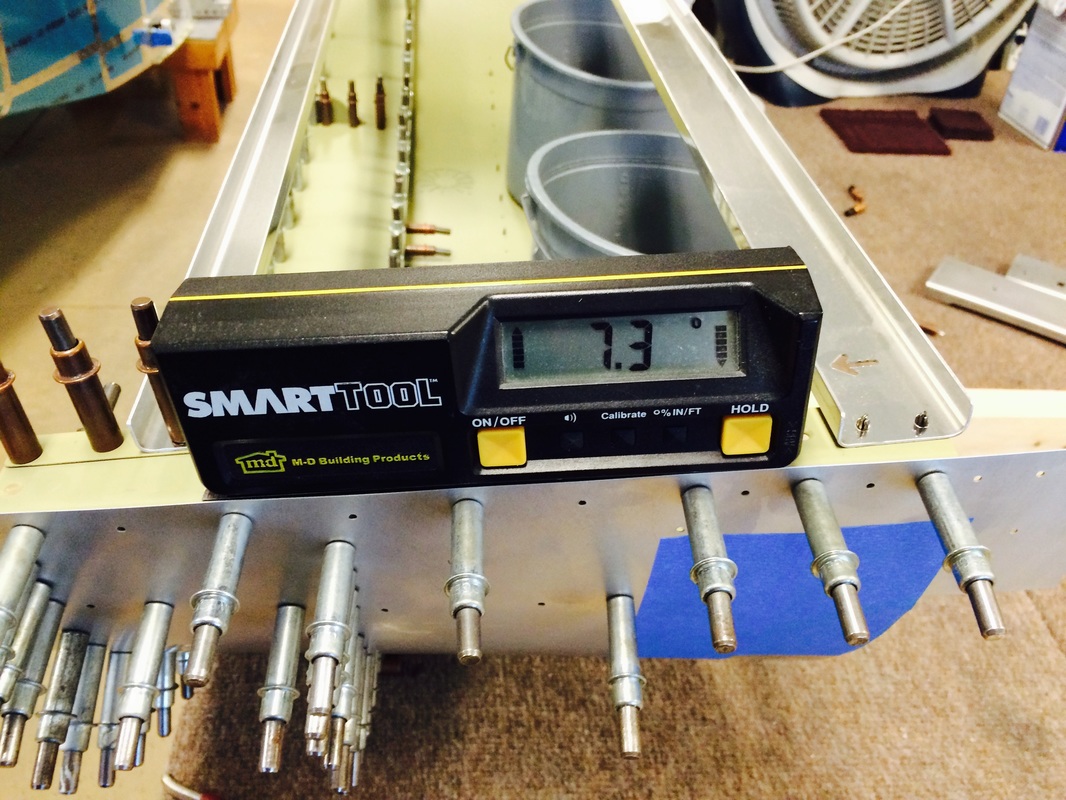
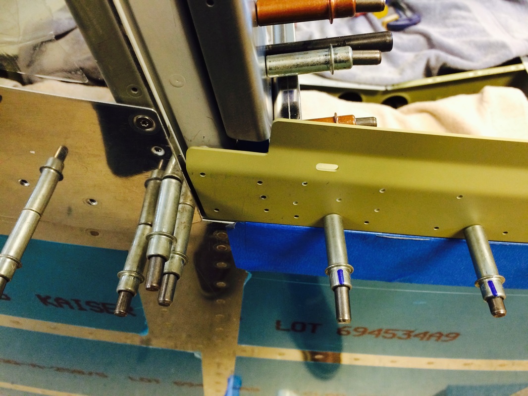
Staring with a level table to measure the 2 bottom rail plates to insure they are the same
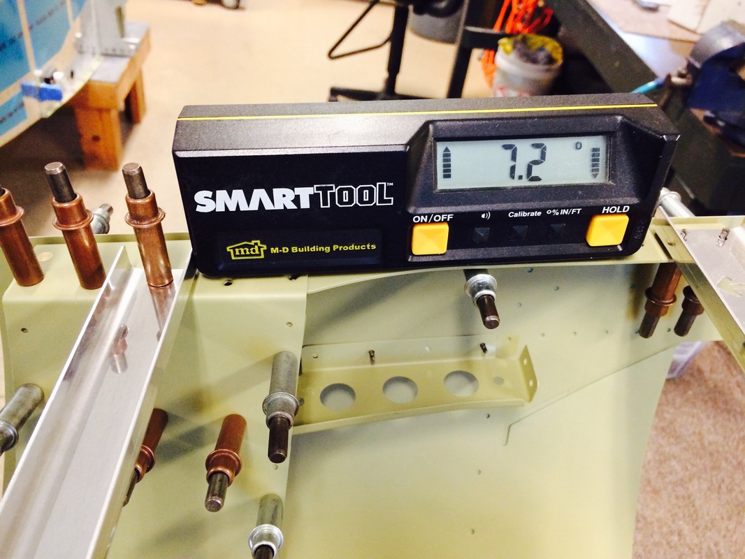
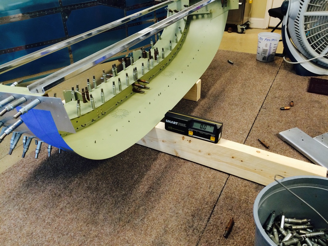
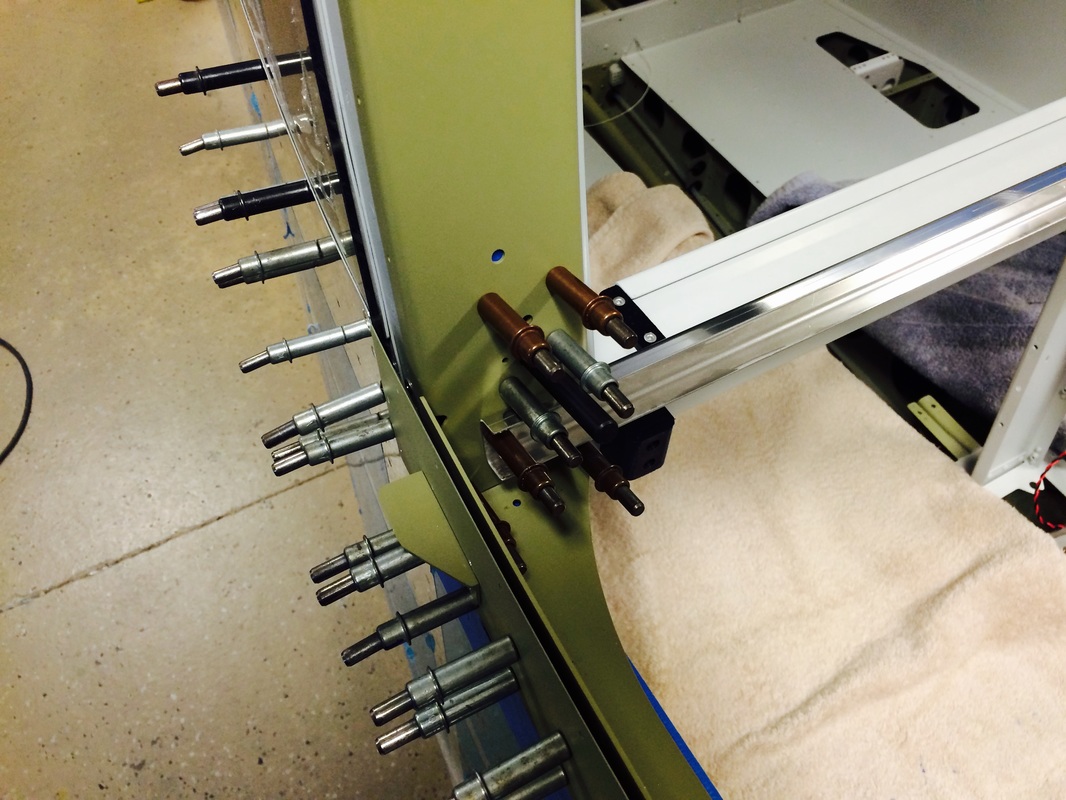
Left rail while drilling the the closeout box at 7.2 degrees
This s as close as I can get, 1 tenth of a degree.
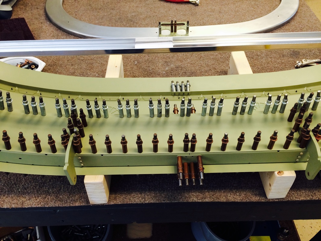
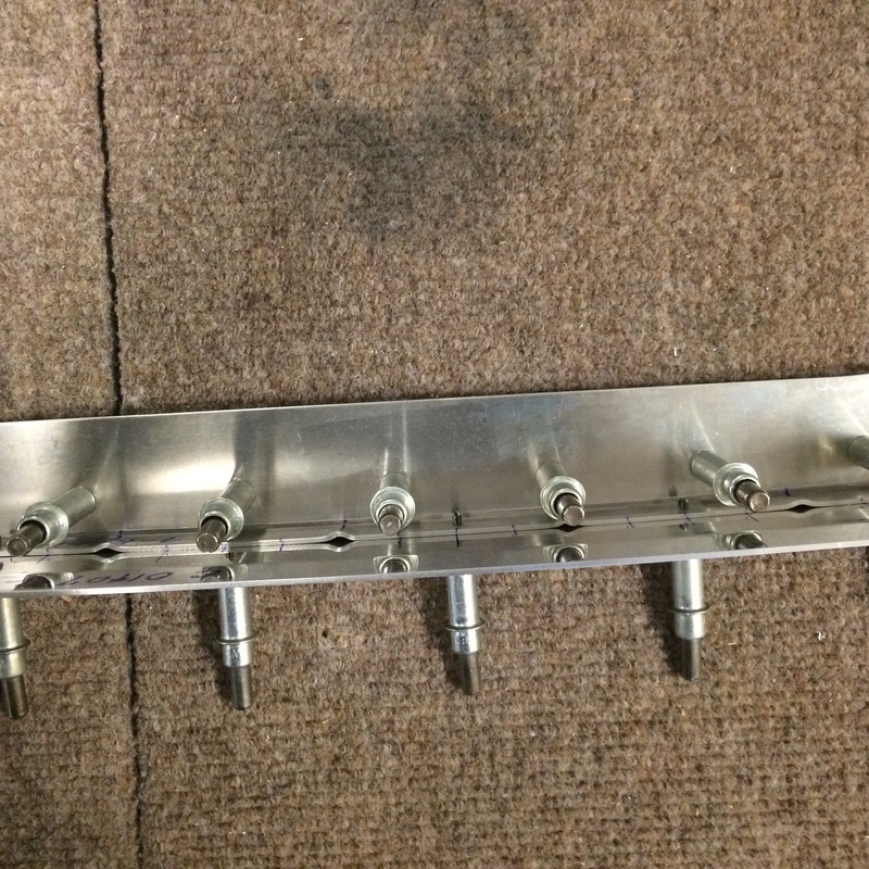
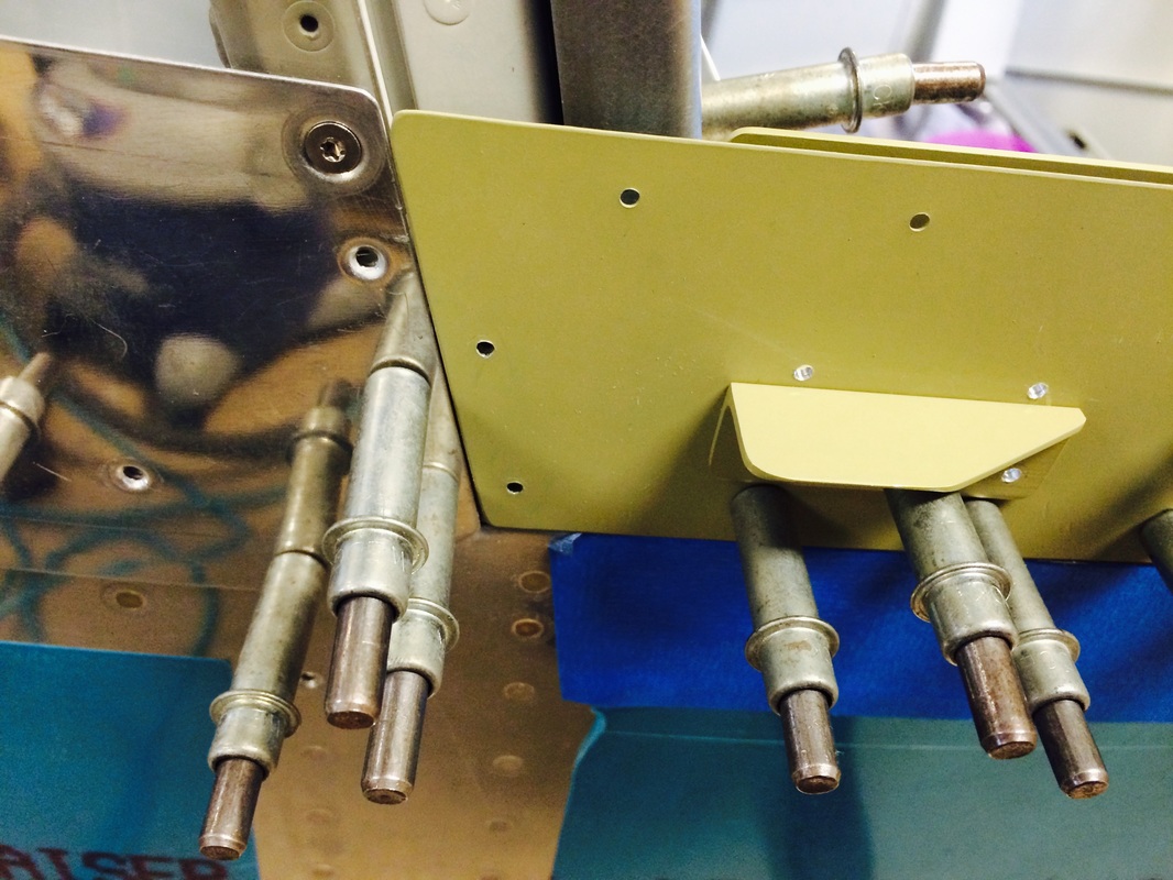
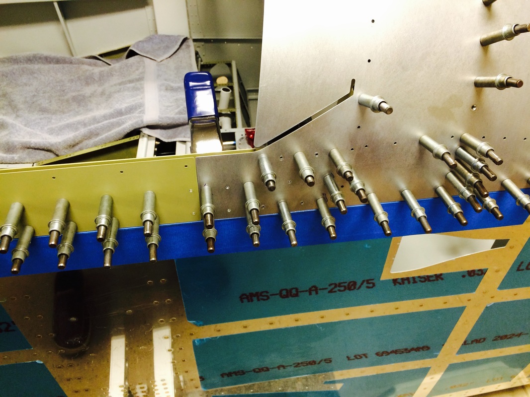
After drilling, with 1/8" and 3/32' drills, they will get drilled one more time with # 30 and # 40 to full size
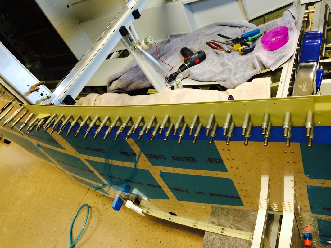
Lots of drilling, but eventually it will be come very rigid after riveting
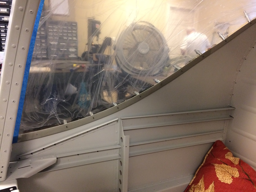
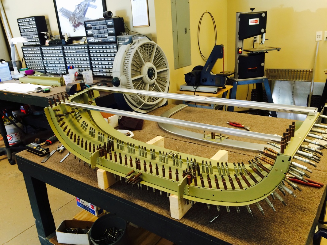
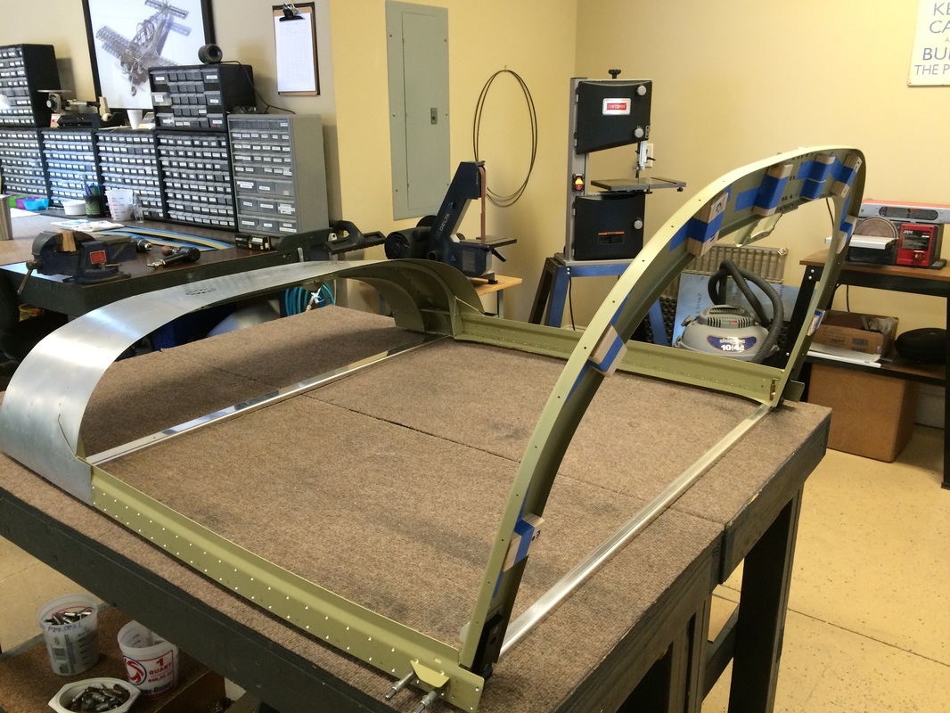
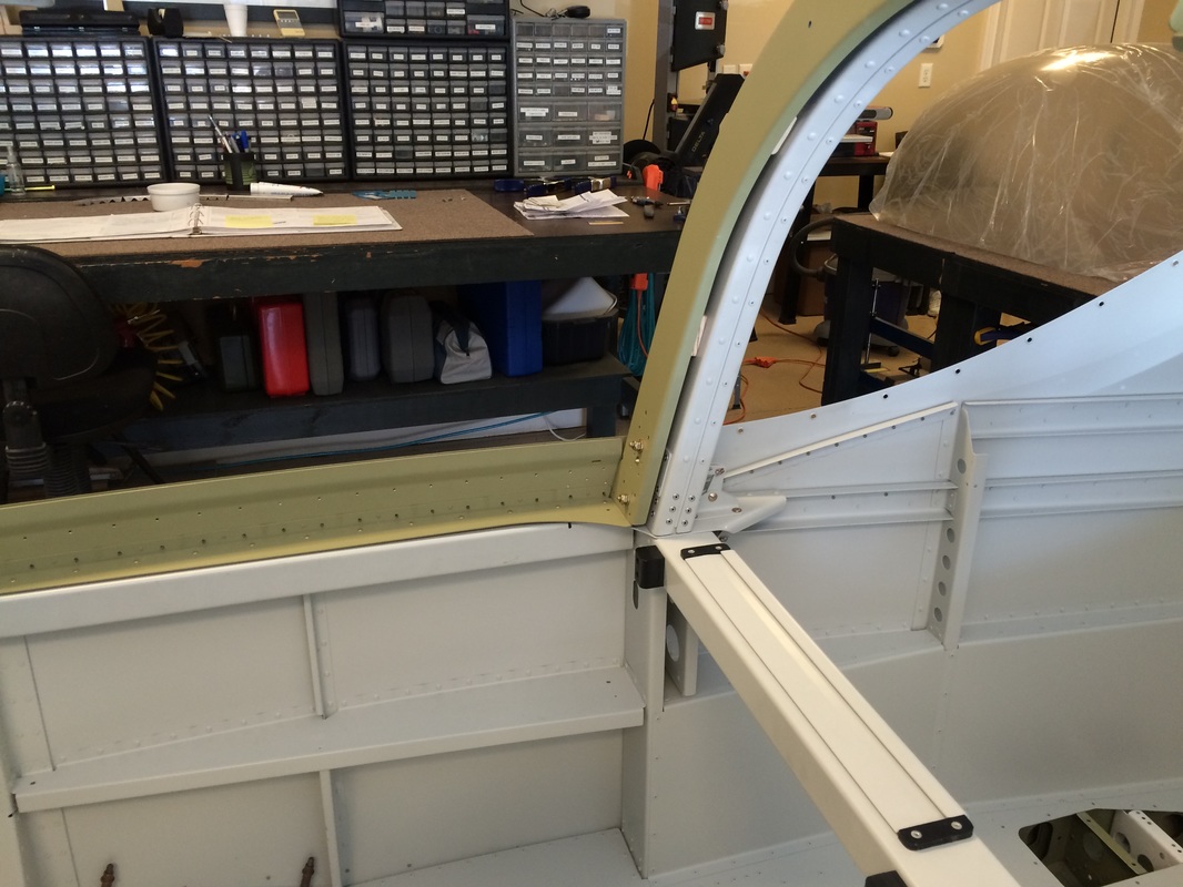
Working to get the canopy frame to match the fuselage side
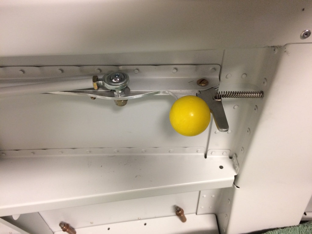
Canopy lift handle.
Side rail skin that traps the canopy between between the rail and the skin
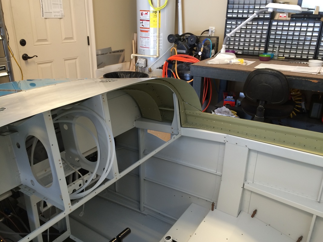
This is the canopy rear frame that picks up the rear of the canopy bubble and where the latches lock it in place.
The side rail attach to the front instrument deck
Canopy handle after riveting to the rear canopy frame
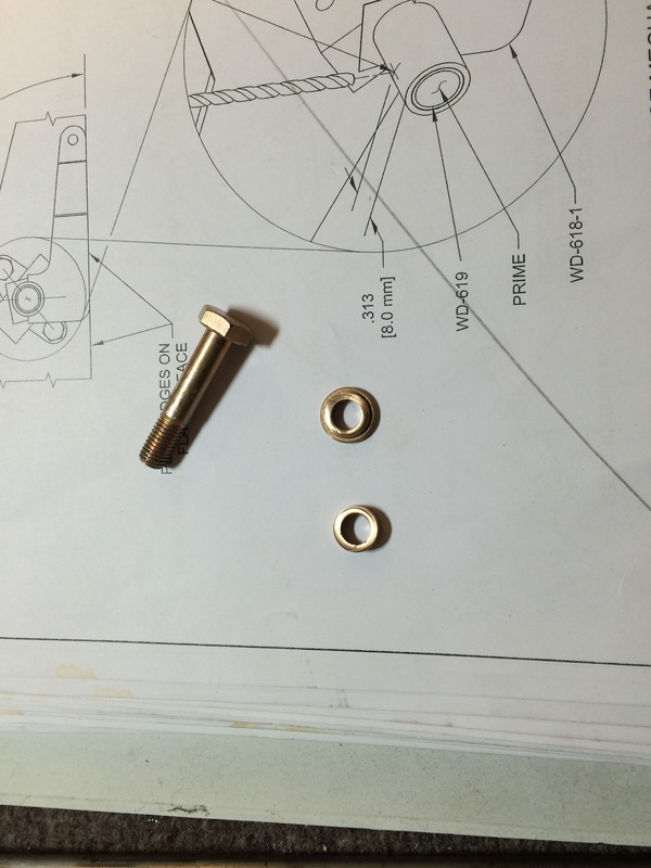
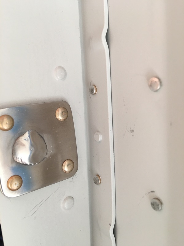
Since we are not using the ejecting canopy, we modified the shouldered bronze bushing splitting it in half and using it on both sides of the canopy hinge. This keeps the bolts bushed all the way through the assembly. Nice and snug and friction free.
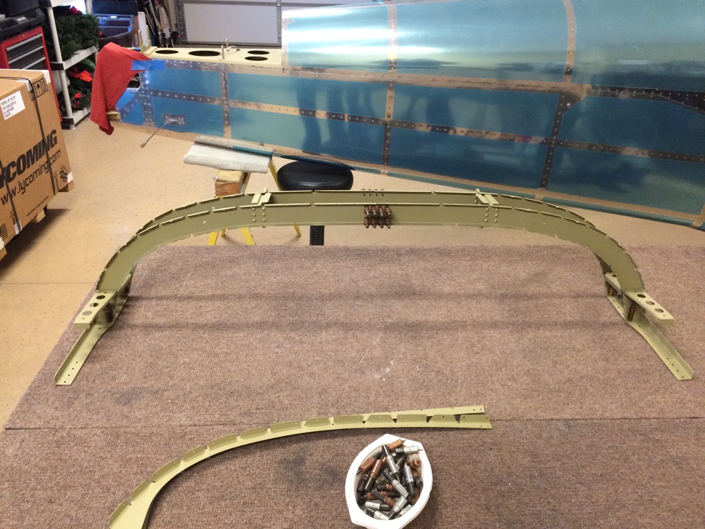
Today was the day to rivet all the canopy frame parts together following the very specific steps in the manual to keep the farm from twisting. We held the tolerances well and the sill on the left and right side are within 1/10th of a degree.
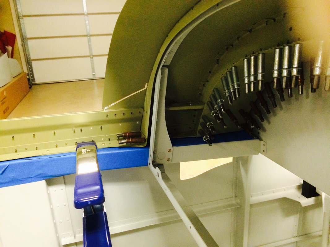
This view is the canopy frame box riveted except for the wire attachment locations
The rear frame is inlace and riveted to the side frames
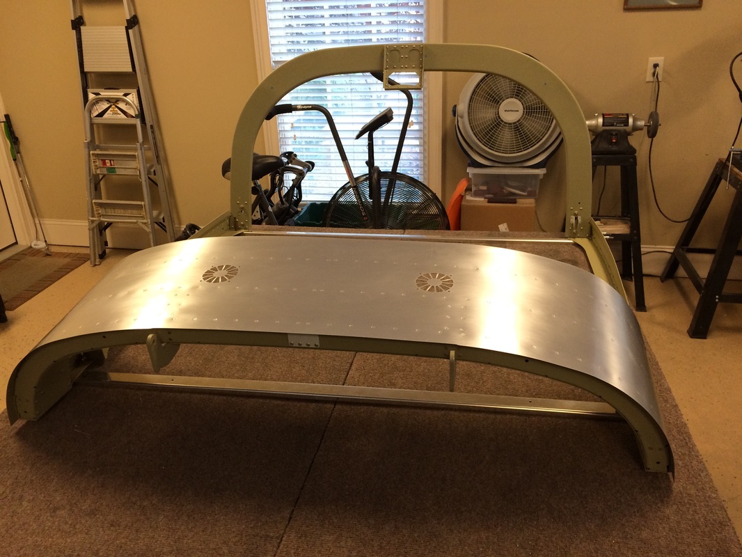
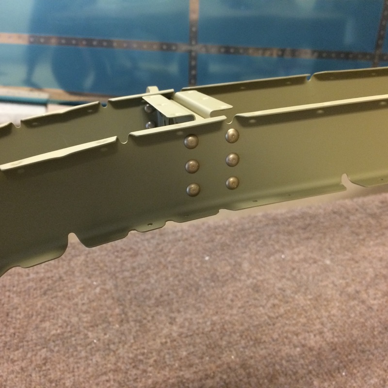
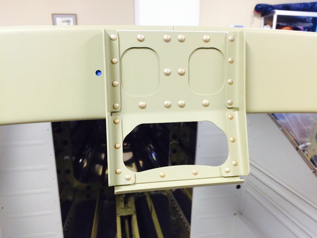
Front view of the assembly looking aft.
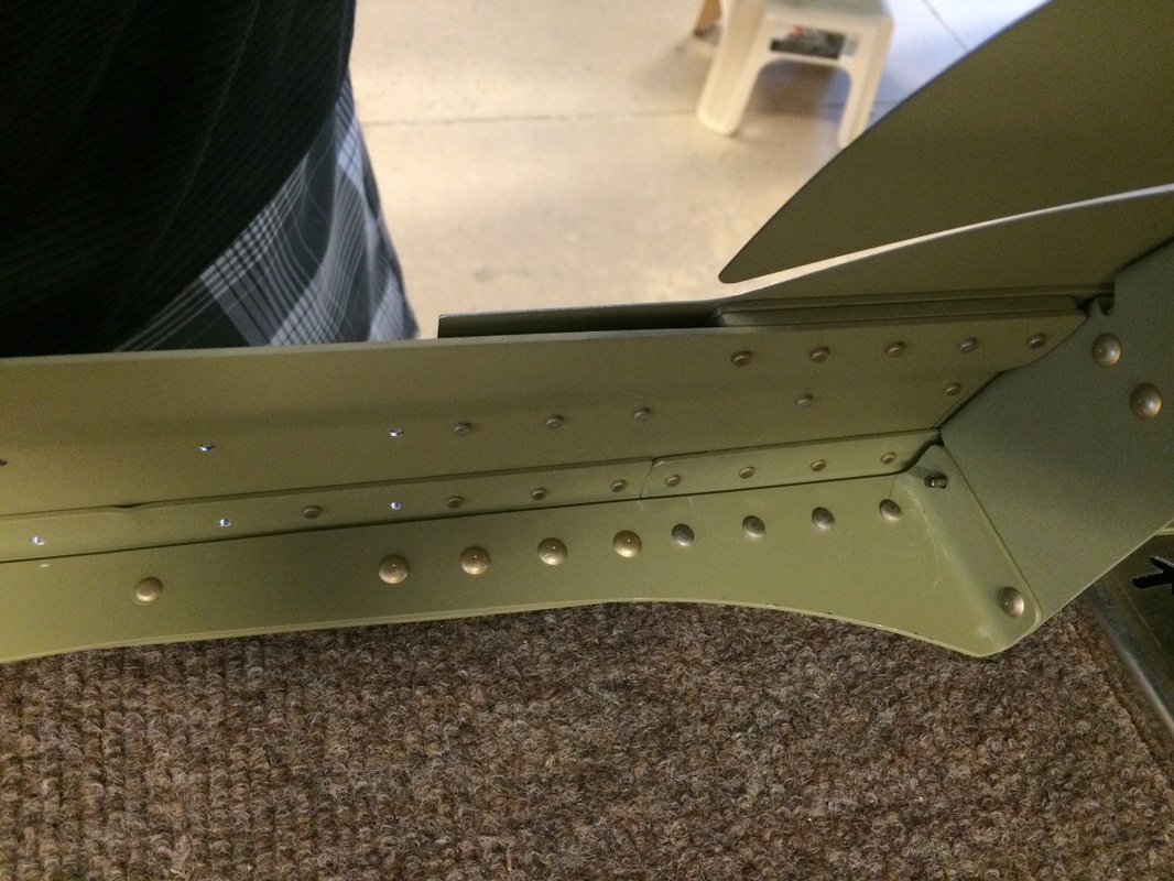
The small button heads are actually the manufactured head of a - 4 rivet using a button head rivet set to form the round manufactured head. It will look better than a flat head, especially after painting.
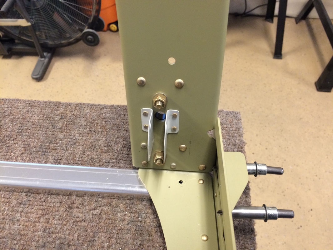
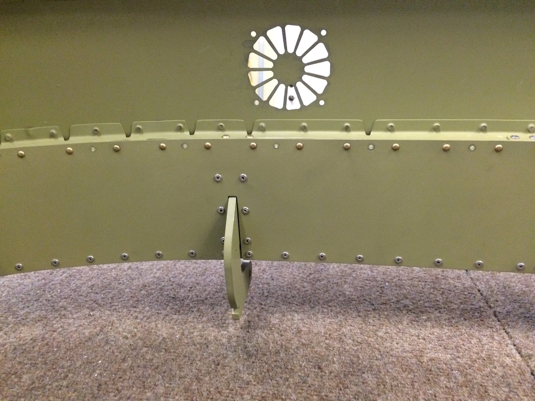
Rear canopy frame showing the switch bracket for the canopy lock.
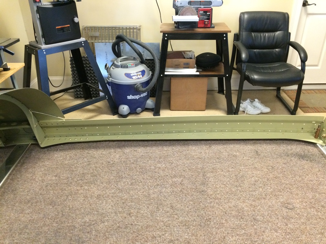
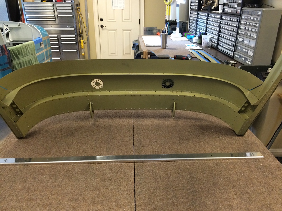
Canopy side rails before attaching the exterior skins.

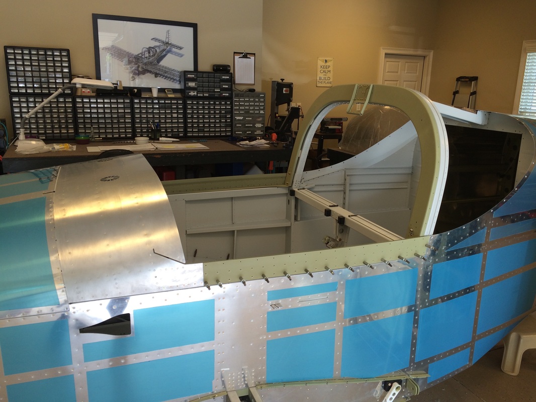
Fitting the frame to the fuselage has been a real challenge. We followed the plans exactly, but the fit was not good aft of the front section. If I had to do it again I would build it on the plane to insure the fit. I will probably remake the canopy side skirts to reduce the visible gap. There is plenty of room for the gasket under the bottom of the assembly.
I made the canopy handle twice. The first one with the kit was not flush with the skin. I worked fine, but I wanted it to look good and we had plenty of 1/8" aluminum own hand. This is the new one flush with the skin. More better!
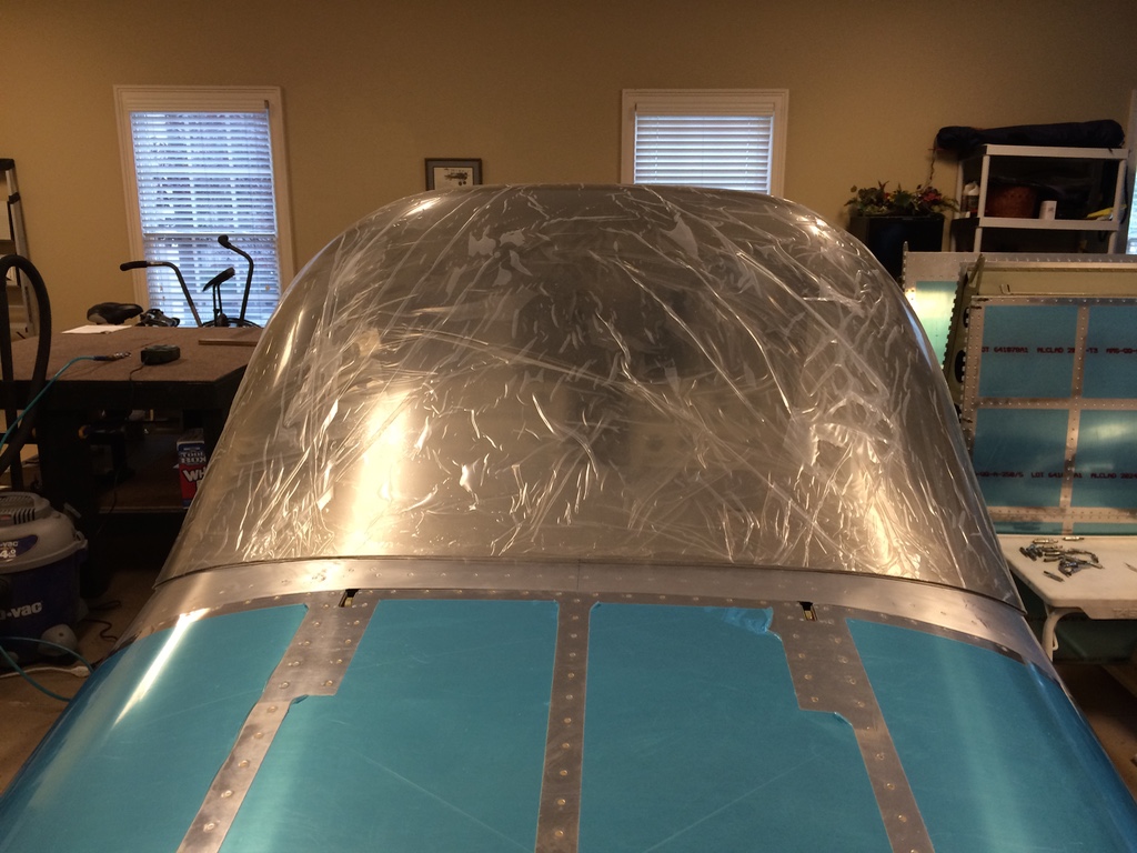
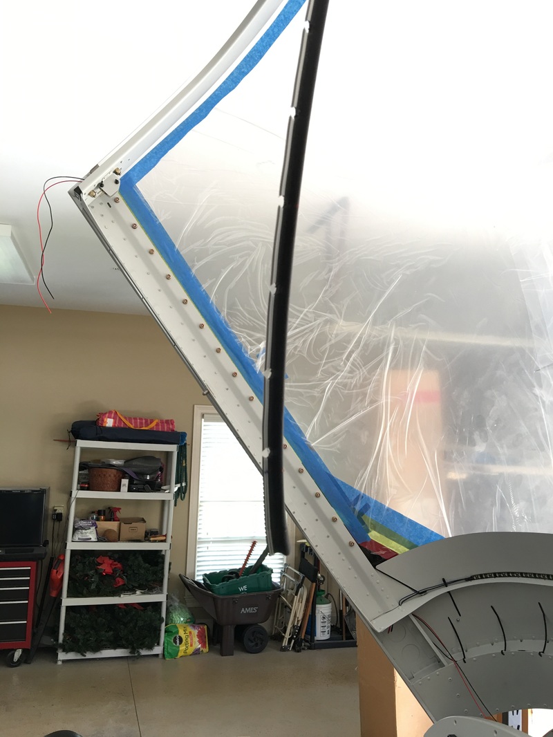
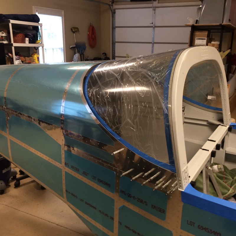
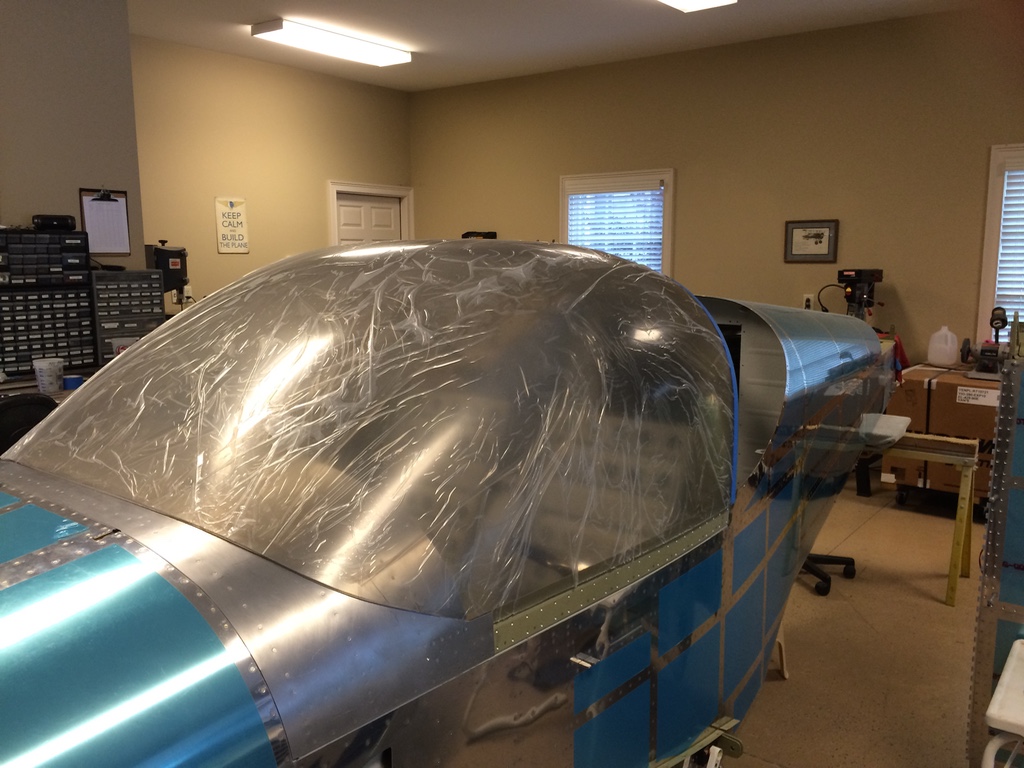
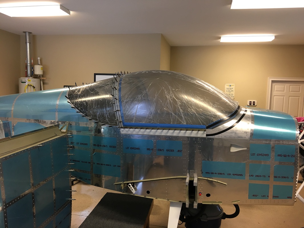
We started to fit the canopy to the frame, the fit wasn't bad, but is still needs some work. It will require a lot of fitting and tapering around the urge of the front deck and may need some tapering down the sides to lay flat in the channel.
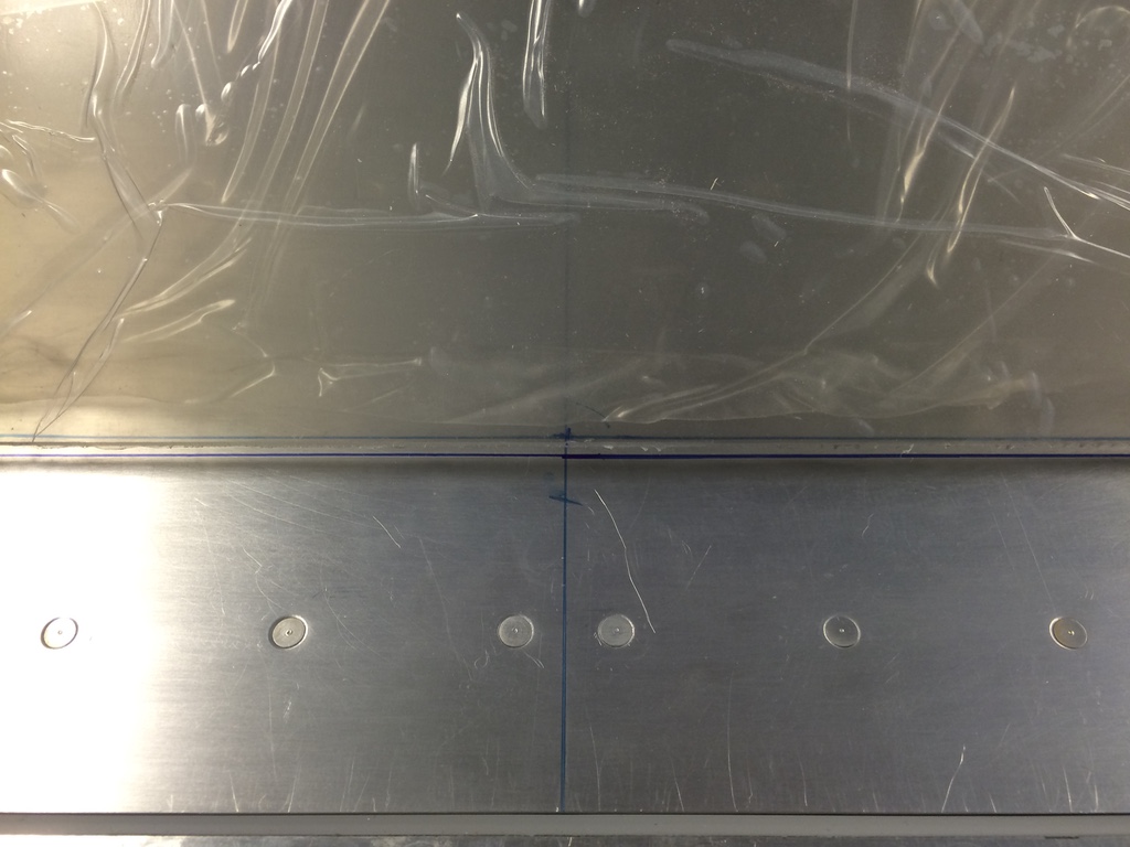
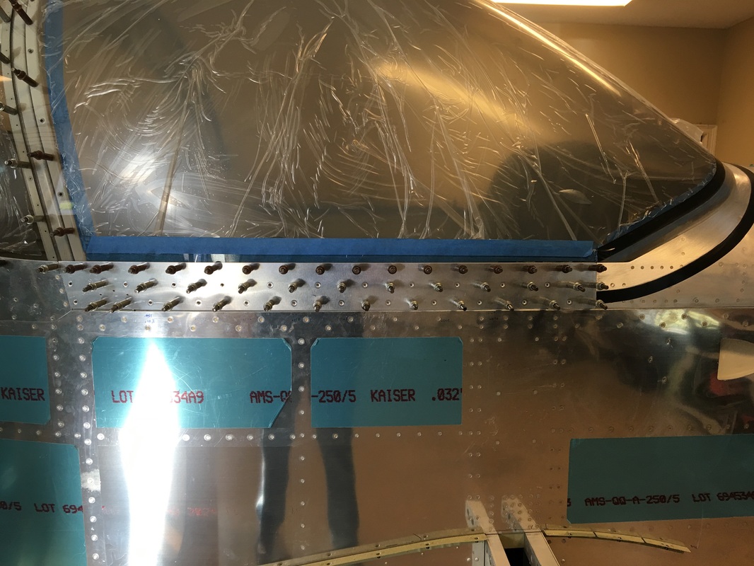
Alignment per the instructions centering the canopy on the front deck and also on the rear bow.
This is how it sits after some sanding, more to come tomorrow
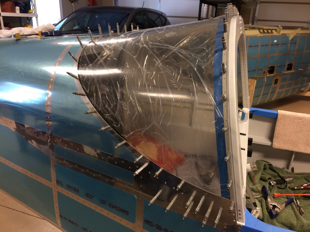
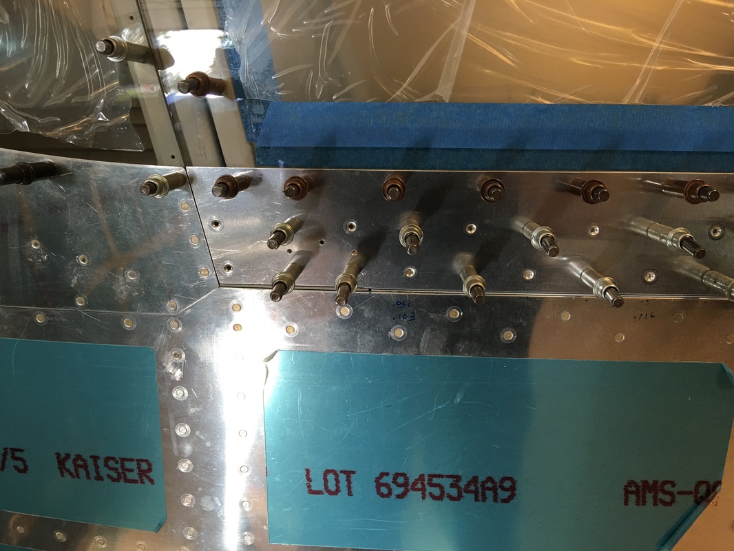
This first round of drilling is complete with #40 holes. We needed a shim on the right side since the it was .15" thick vs the required .17". The left side was .18"
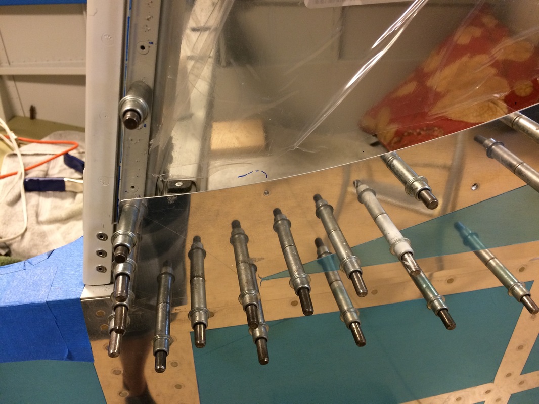
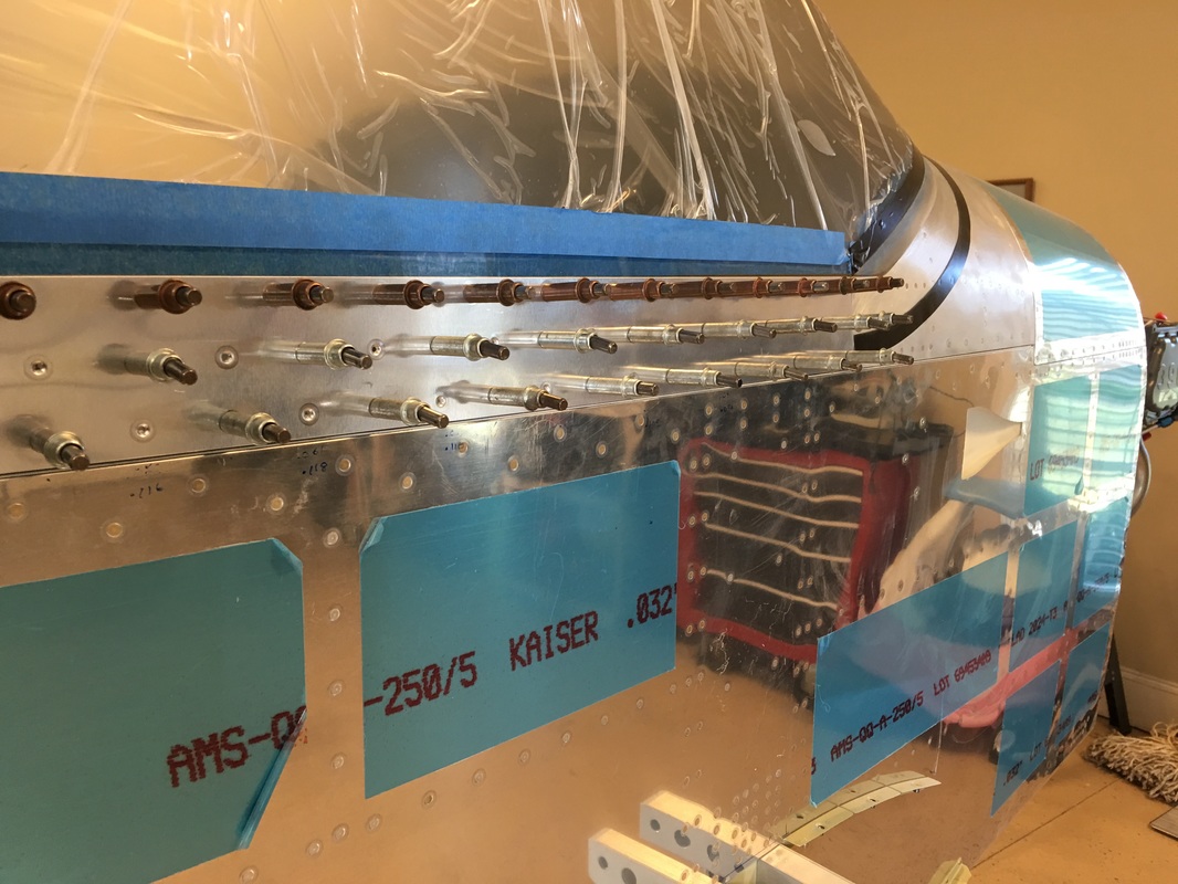
An inside view of the drilling process
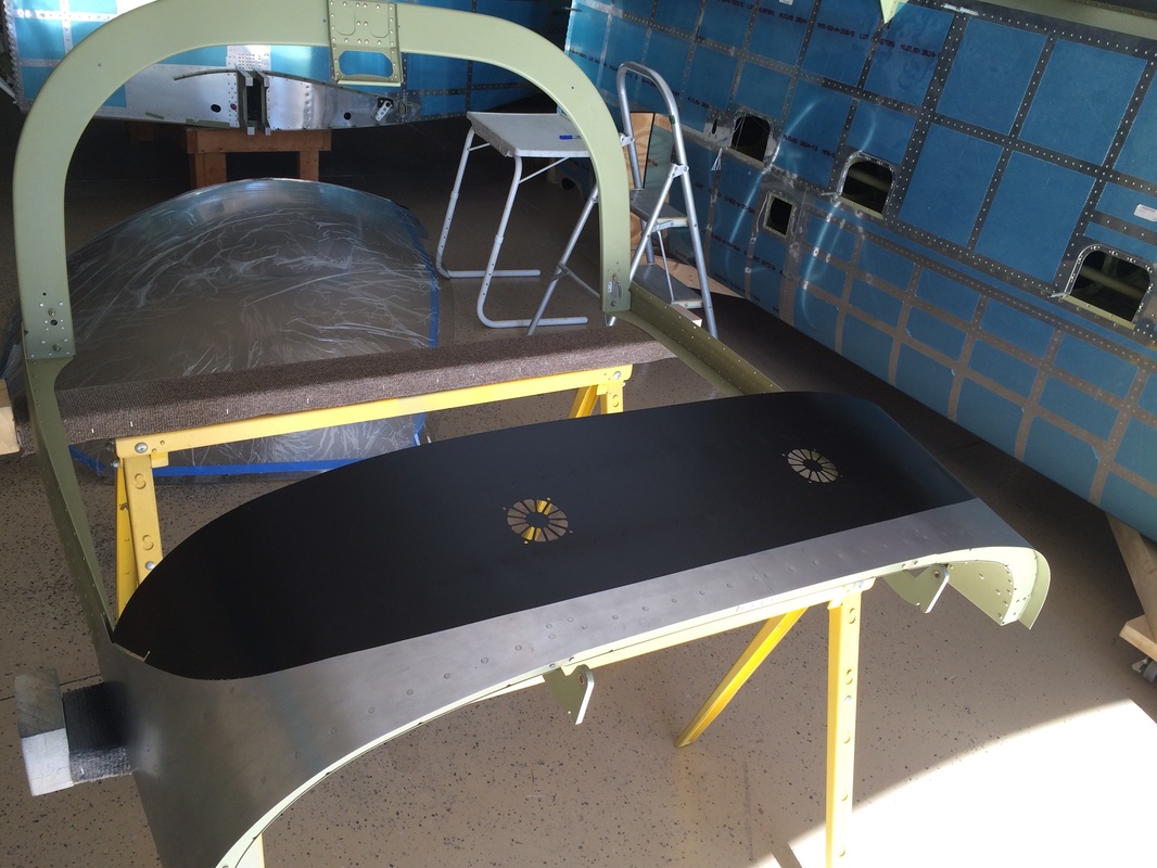
We struggled with the flat/satin paint on the glare shield. The first try for some reason did not adhere well, so I sanded it off and we changed paint, which splattered with the spray gun near the end. It adhered well and we wet sanded and sprayed another coat on and it finally looked good. Painting has not been kind to us on this project. Paints are just not what they used to be because of the changes made to deal with OSHA requirements, I would love to get the old Imron back.
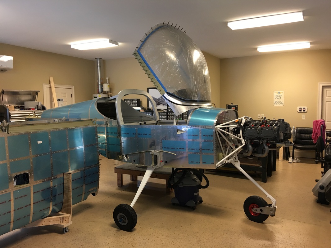
Canopy mechanism is working well and the gas struts seems perfectly balanced for the weight of the canopy assembly. There is some slight rubbing on the way down, especially if you don't pull down on the handle straight.
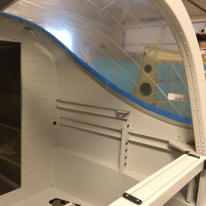
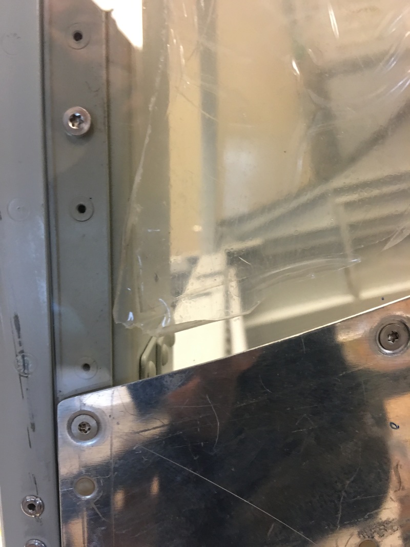
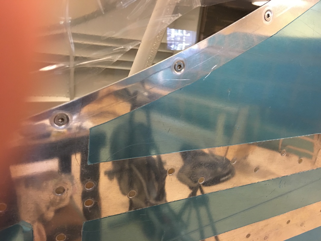
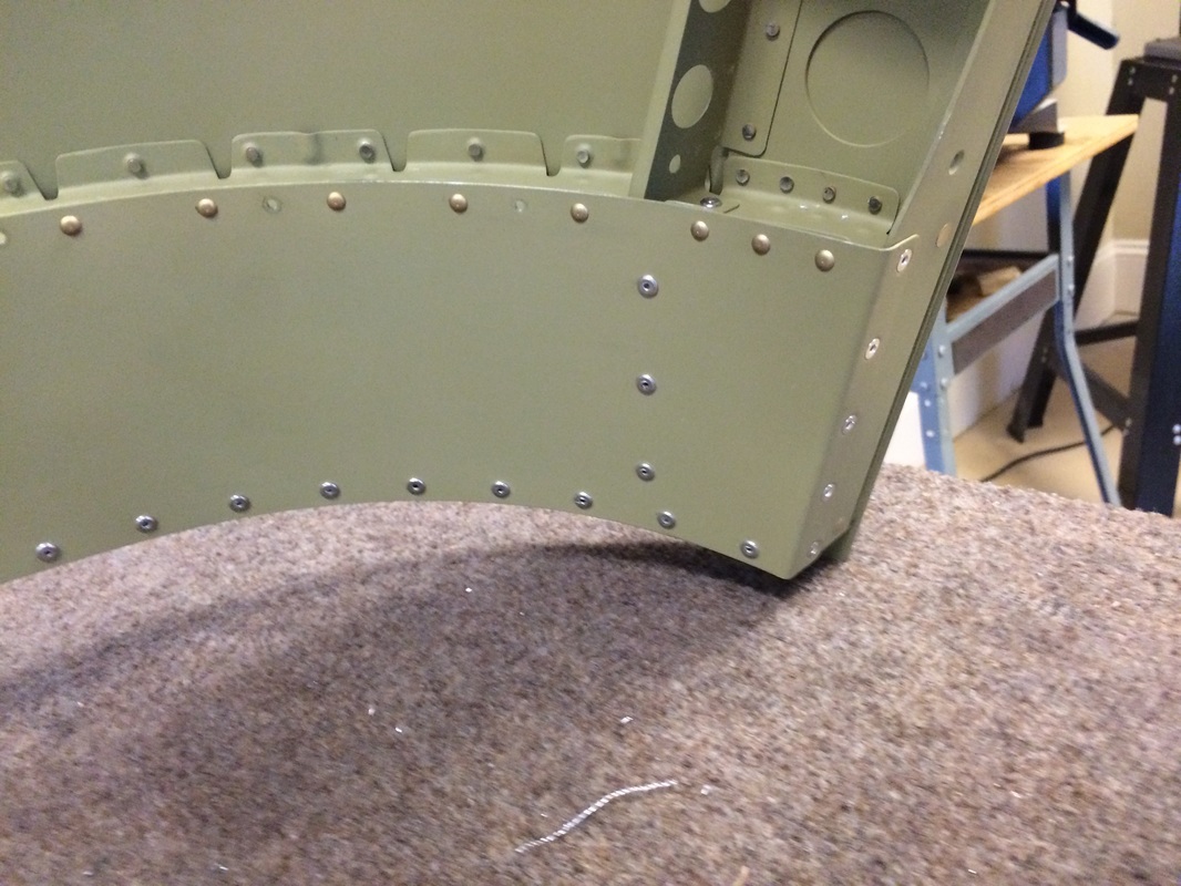
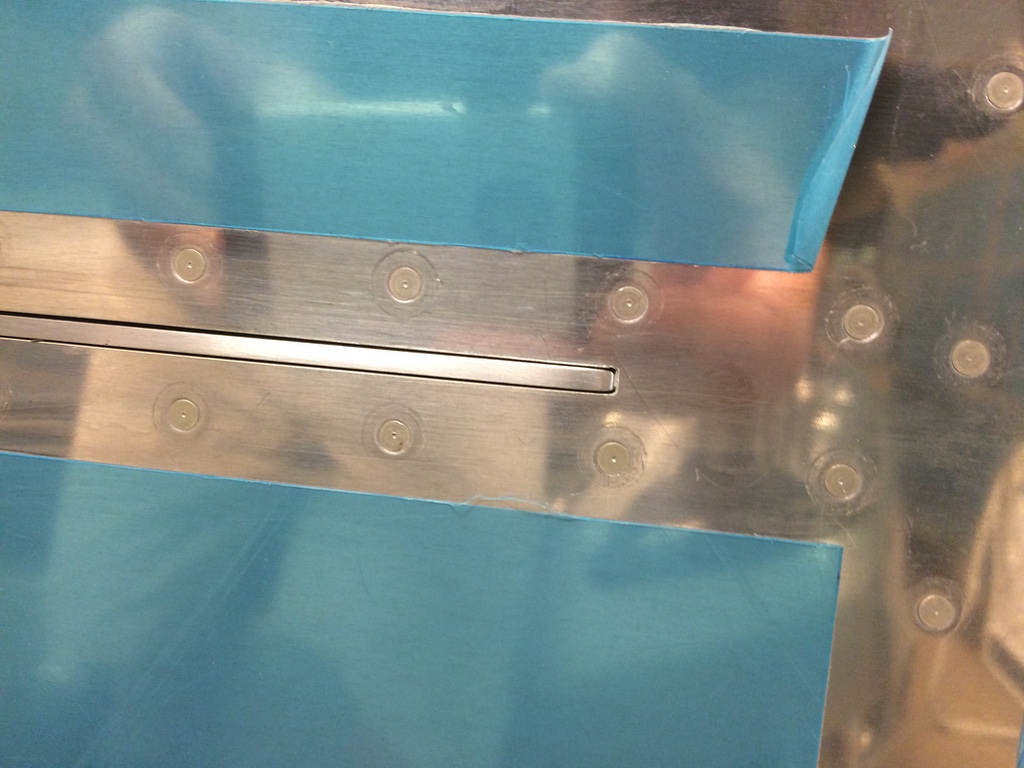
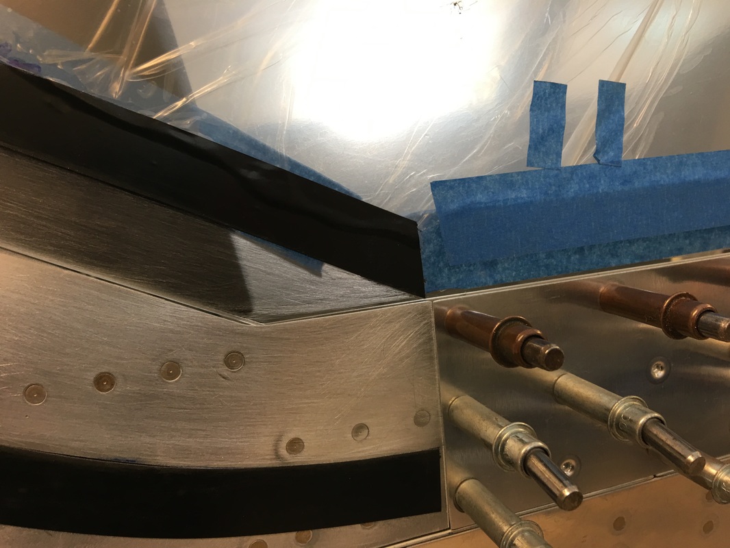
Here you can see the edge of the sill between the canopy skin and the fuselage side skin. I wish they were set back a small amount and the skin then could have butted but I think this will look fine after painting. When I looked at the prototype, there gap was considerably larger, yet looked ok from a distance.
We struggled greatly getting the canopy to fit properly. There is just so many things that need to come together to have it open and close without interference, and yet have a nice appearance at the seams. We finally decided that the best route was to get the canopy frames aligned and function properly with the latches, then get the side skin to fit with minimal gap at the sill. I think if Van's would add a little extra material on these side skins on the bottom, you could then file it back to match as required.
I ended up making new side skins match drilled to the originals and added an extra 3/32" to the bottom of it which I filed to match the top longhorn canopy sill. This worked and there is now minimal gap from the outside view, yet 3/32" behind it for the gasket.
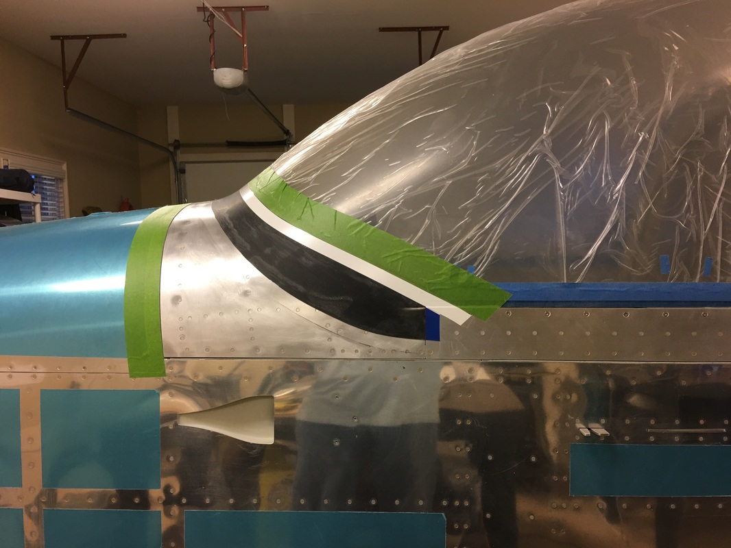
We are preparing for the from fiberglass fairing layups by sanding with 80/100 grits and taping per the instructions and templates
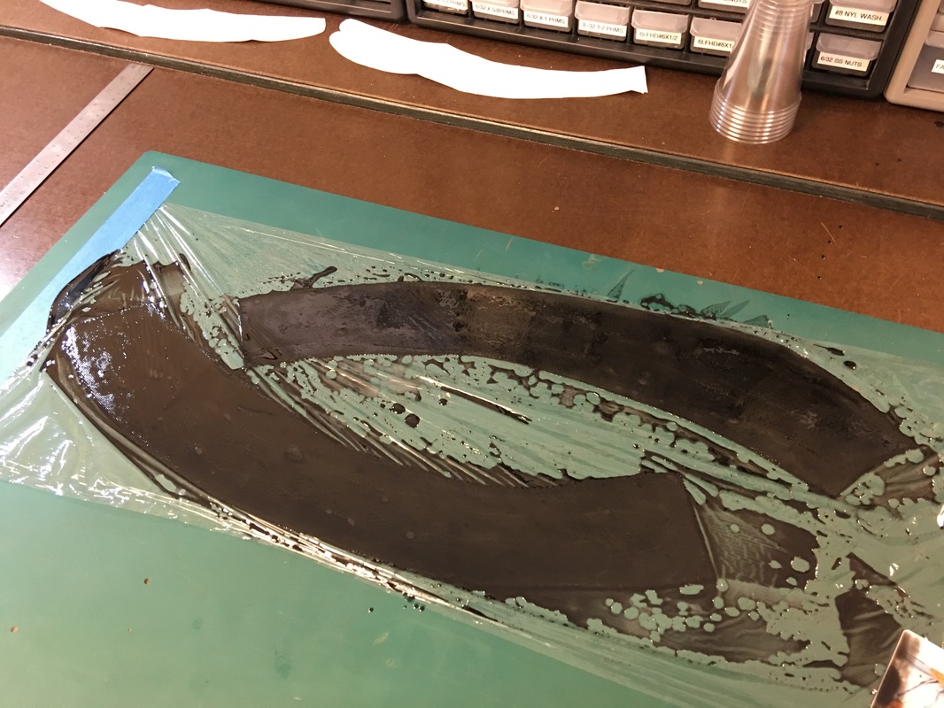
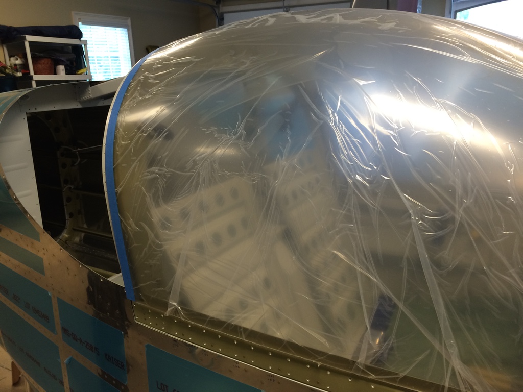
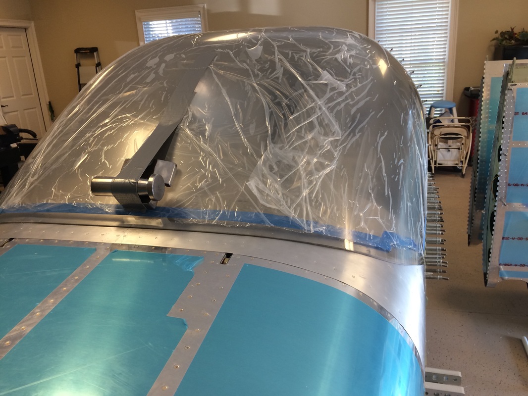
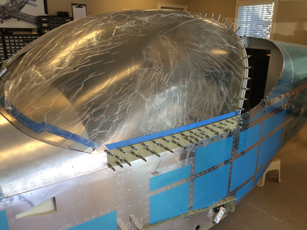
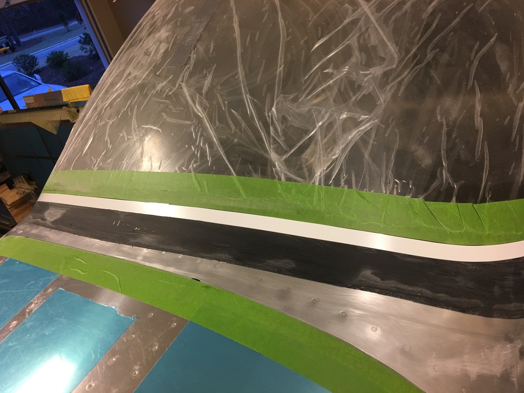
These are the first glass layups. We are using West epoxy and 8.5oz cloth per the plans. This is the start of the sandwich layer in the Saran Wrap to keep the cloth in the proper shape. We are using black dye on the first two layer only for a neat appearance inside.
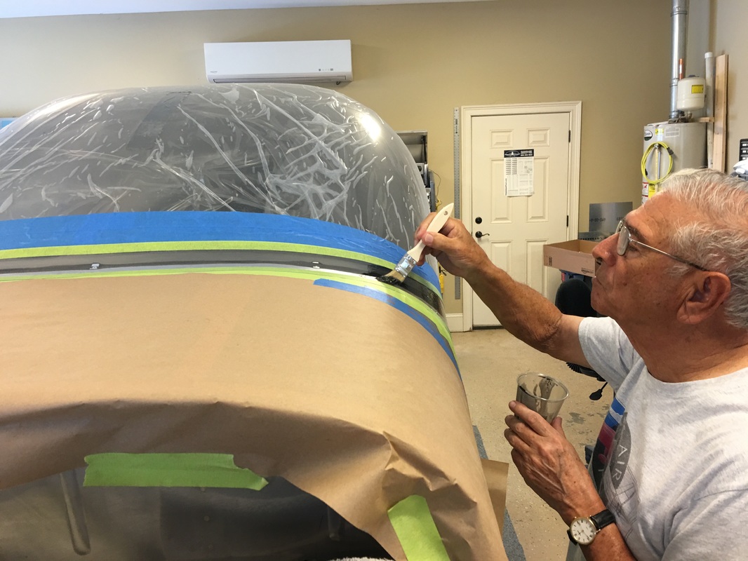
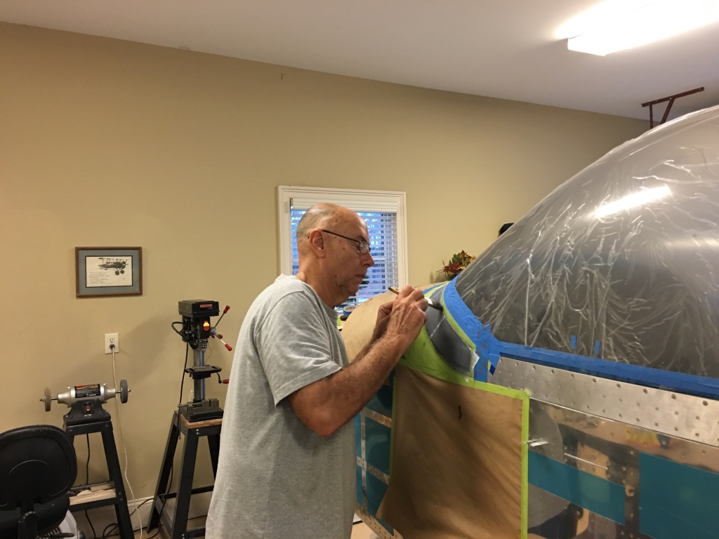
Rafa brushing on a coat of black epoxy in preparation for the first layer of fiberglass cloth.
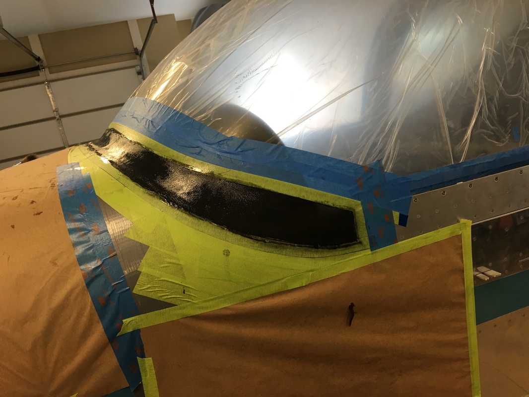
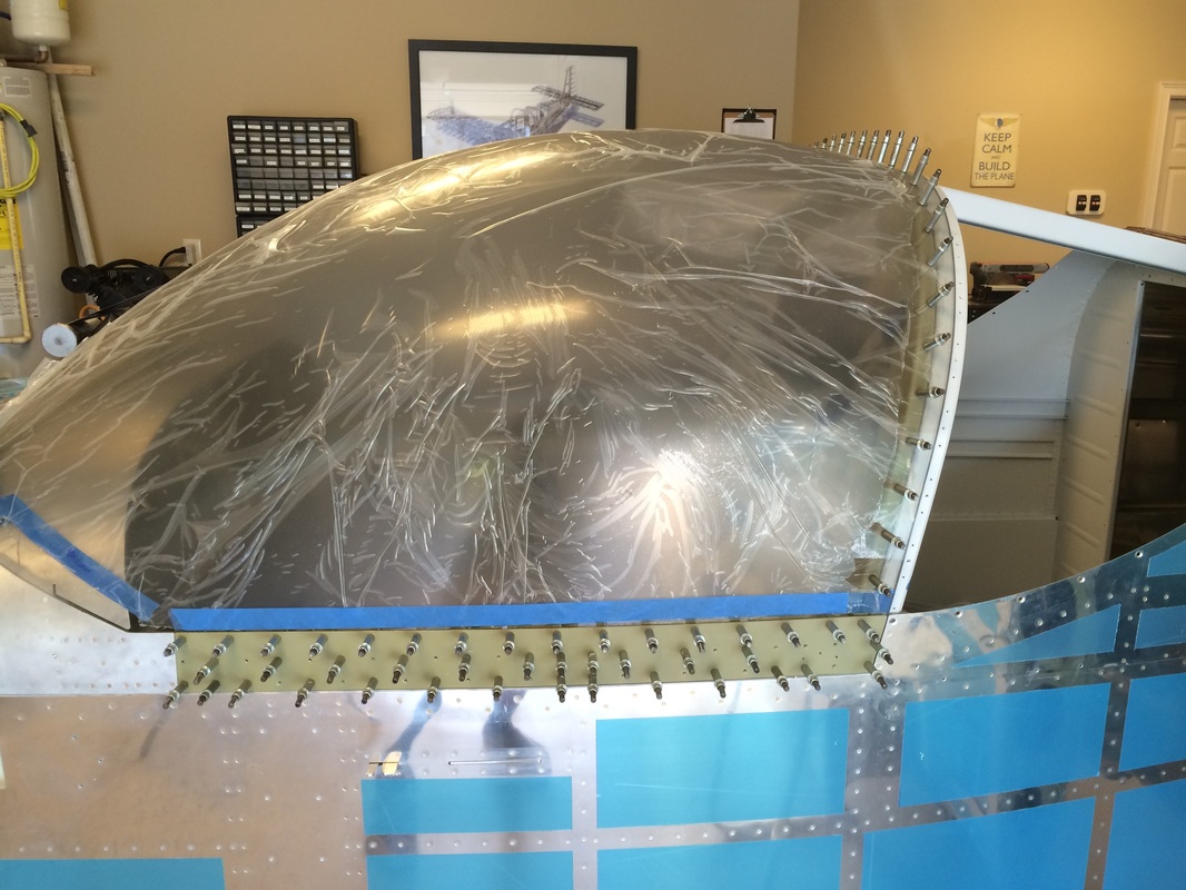
This is what is looks like after two layers. Next are the radius fill in pieces using clear epoxy and after we get the right shape we add a final layer of peel ply to suck out the excess epoxy and leave a sand-able and smooth surface.
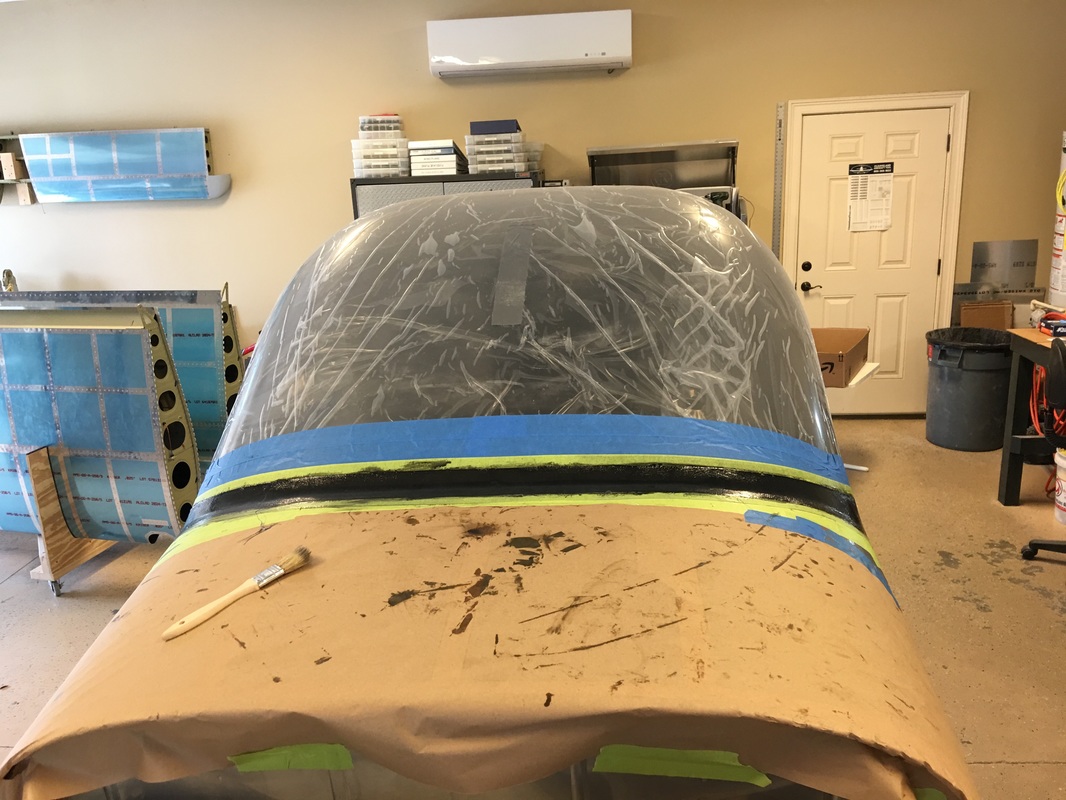
Six or seven layers of various widths of glass cloth and this is what it looks like.
Carl adding the peel ply which will be peeled off after curing.
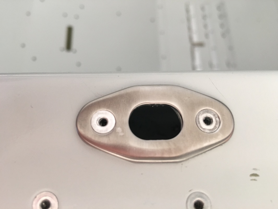
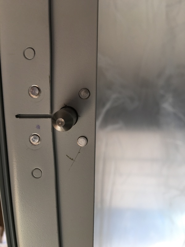
The canopy alignment pin retro fit after installation. This is not as straight forward as I thought. Make sure you rub strips are in place before marketing where the pin go in the sill and that both bottom frames of the canopy match the fuselage sides.