Flaps - Section 21
Vans new slotted flap design
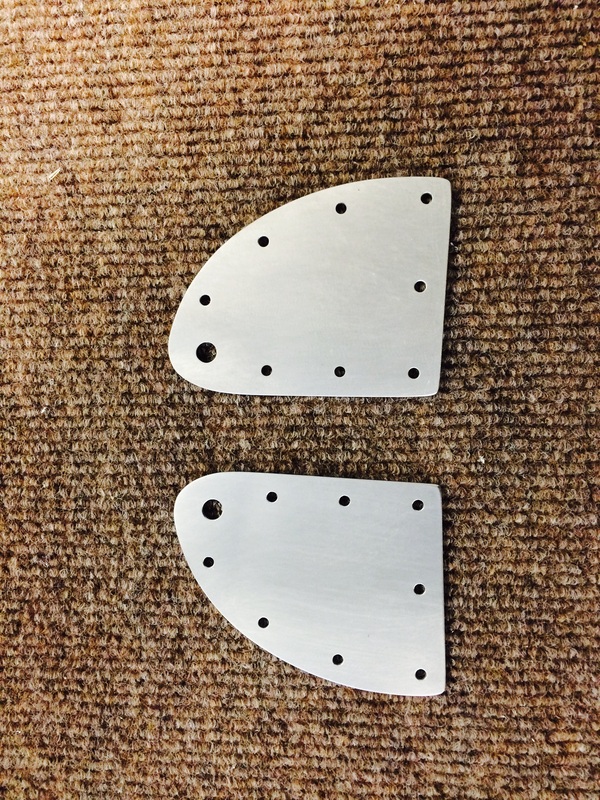
Vans supplies 4 these doublers with 3/32 holes near the large holes for plate nuts, but I ended up countersinking all 4 in error. So rather the replacing the 2 that did not get plate nuts with more holes that are not required, I made up new ones without them. So now the rod end bearings will not be over the 3/32 holes. Does it matter, probably not, but it has to be better with no holes if they aren't needed, right?
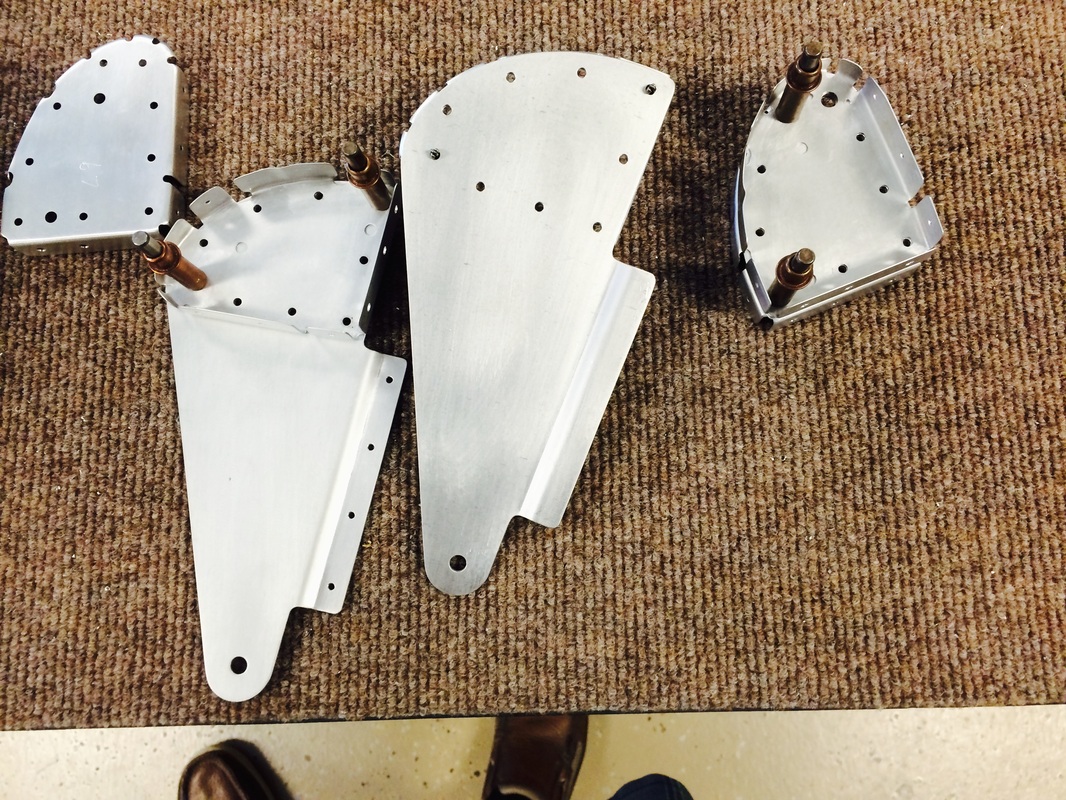
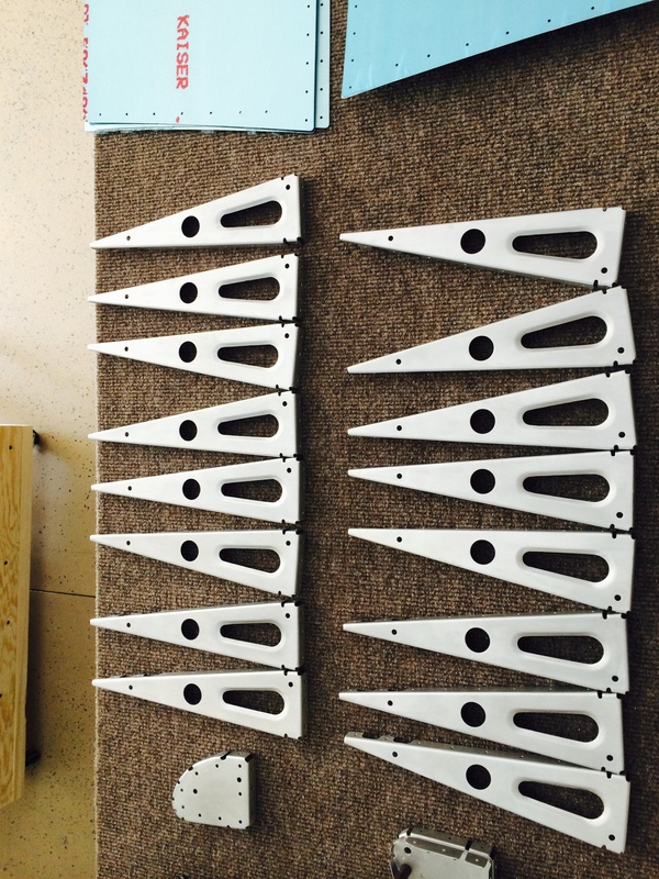
These are all the flap parts on the front of the flap spar, ready for AKZO primer.
Flap hinges. The bracket without the holes in the tab will get match drilled during assembly.
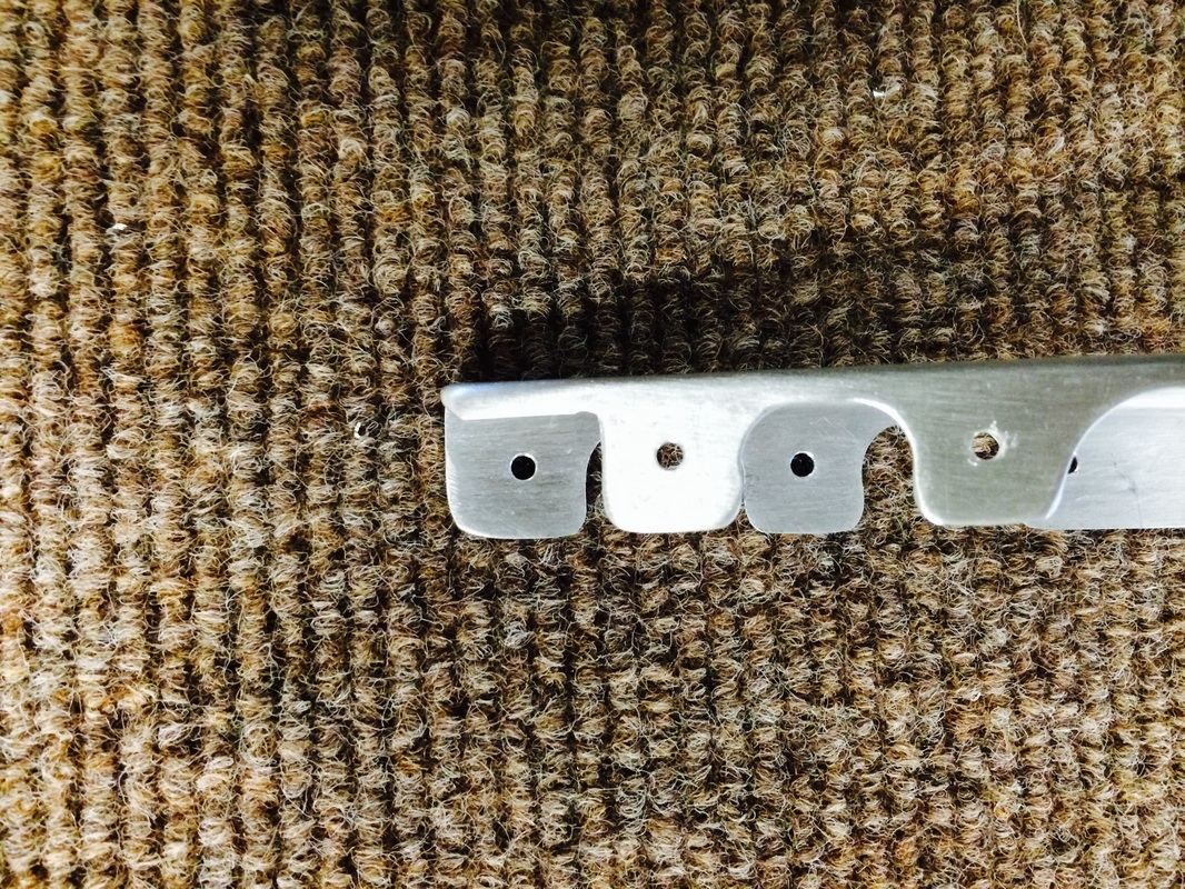
This is a view of the rear flap rib where you cut off the tab on the top. I ended up using a Dremel cutoff wheel, but I put a piece of scape metal under the tab to protect the bottom tab. This worked well.
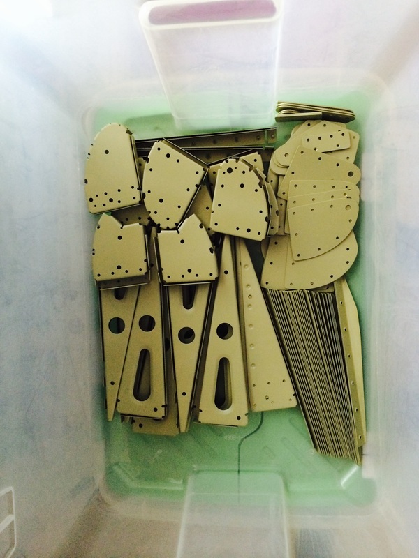
Flap ribs after, reaming the holes to size, deburring holes, edge finishing, buffing and scuffing surfaces for priming.
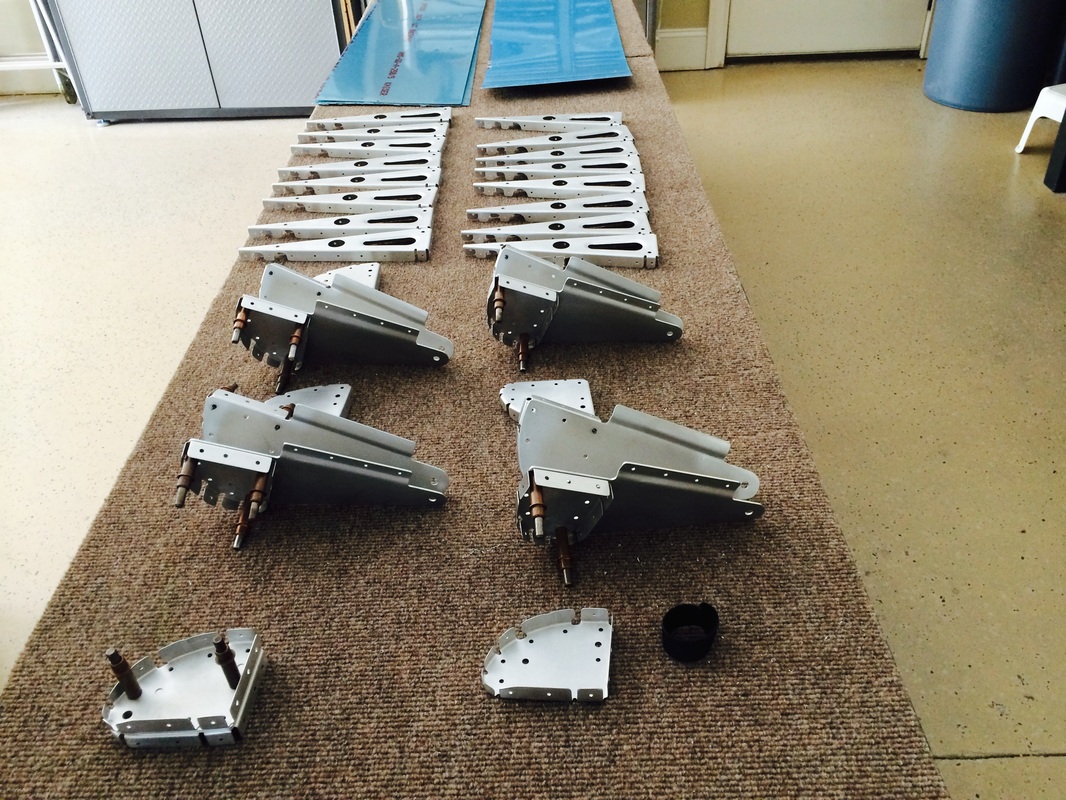
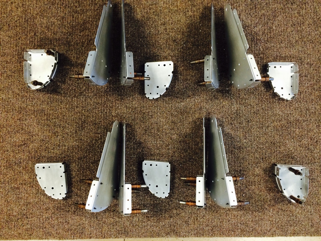
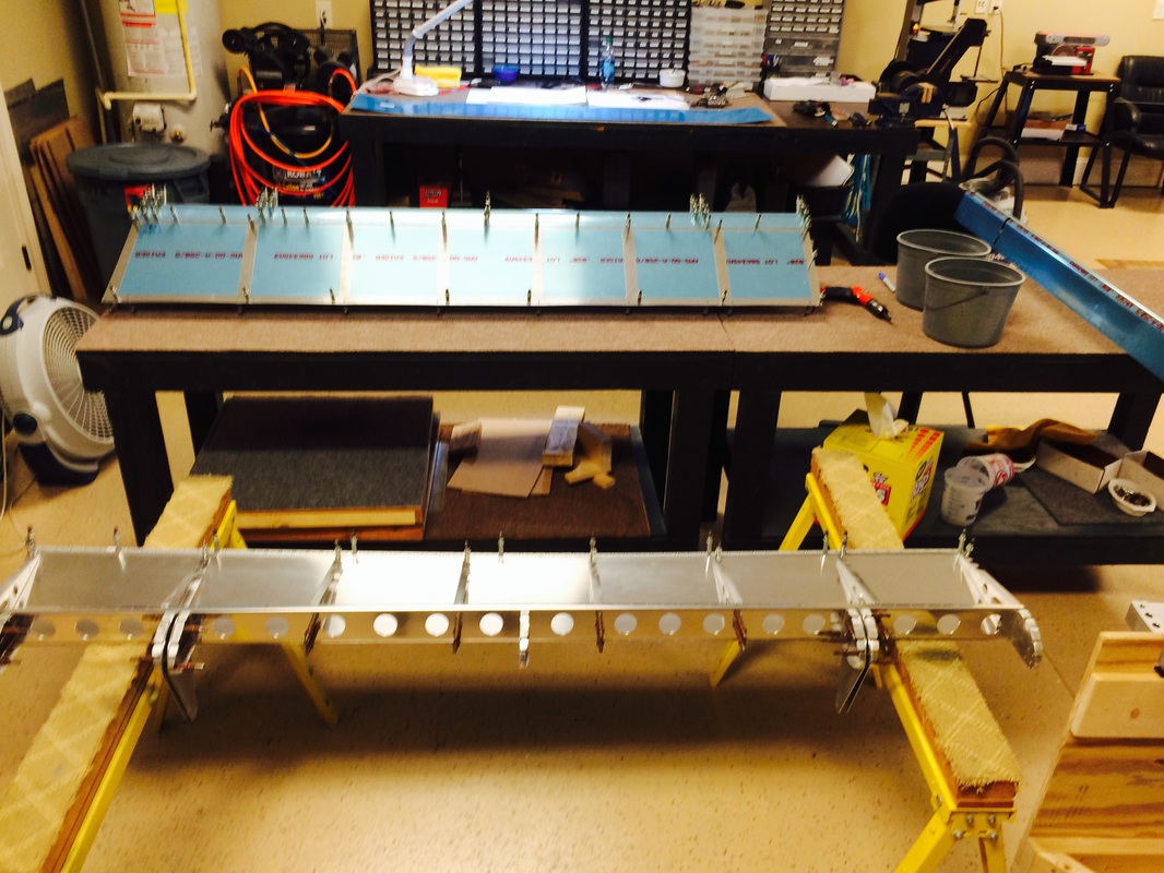
These are all the internal parts for the flap except the trailing edges. There will be fabricated next, along with flap skins.
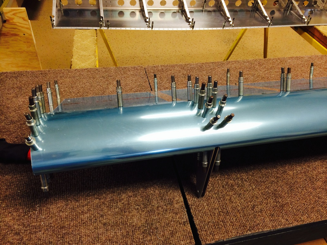
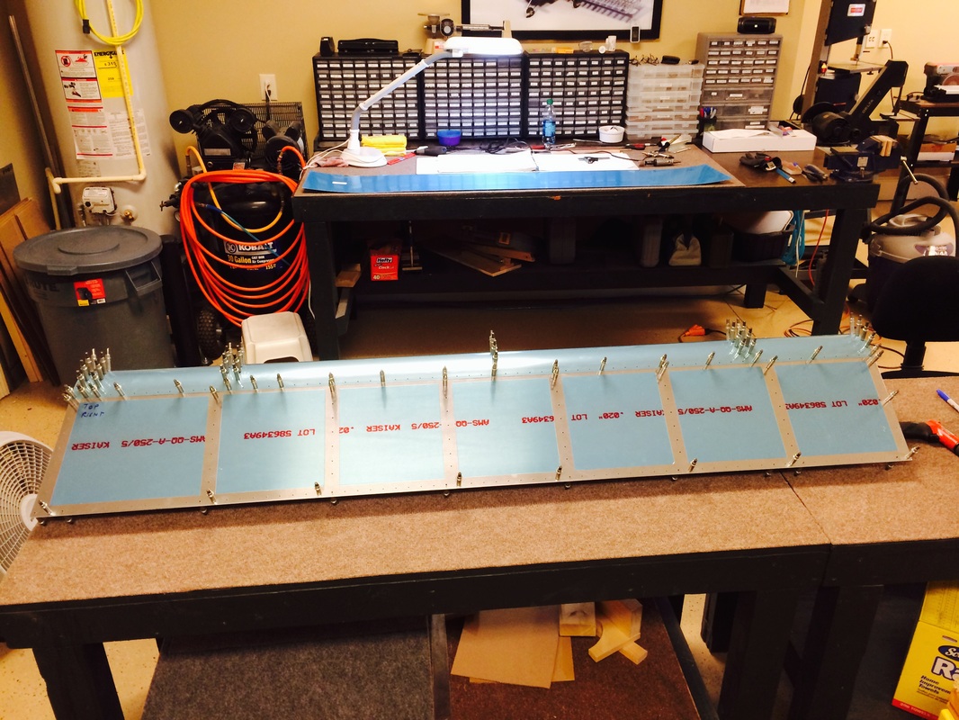
This is where you put the flap assembly together and match drill the ribs and trilling edge

Leading edge is on and match drilled to the ribs. It fit ok, but the rib front edge does not quite touch. This is kind of funny since the plans make a point to buff them round to keep the skin smooth. The holes for the spar are already punched, so you really have no control over the fit of the ribs. Hmmmm.
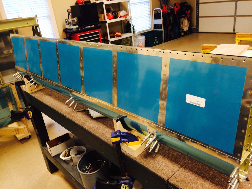
This shows the ribs after match drilling.
Ready for match drilling the trailing edge at 90 degrees to the chord. I think we'll use a reamer and a square.
We primed the aileron and flap internal part together, the flap parts above are in here with and aileron parts
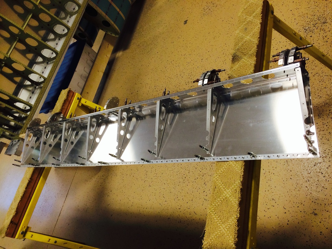
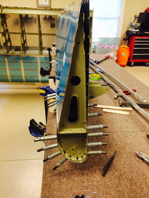
Here we have riveted the main flap spar / nose skin / top skin union
This is riveting the bottom skin the the spar. Not much room, so we used the 12" long bucking bar we bought for riveting the elevator spar. This worked well except for the rib locations. There I used a 1" x 1" x 2" bucking bar we made up with a slightly slanted face to match the spar angle which is about 10 or 11 degrees.
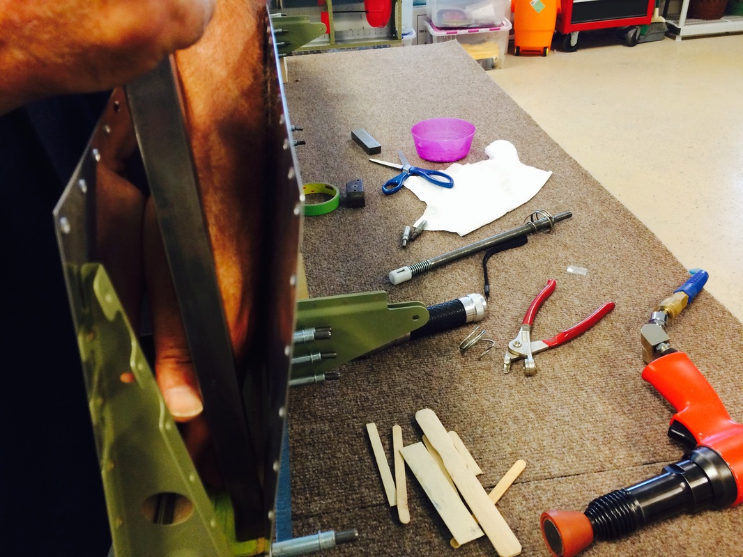
Another view of using the long bucking bar for the bottom skin / spar junction.
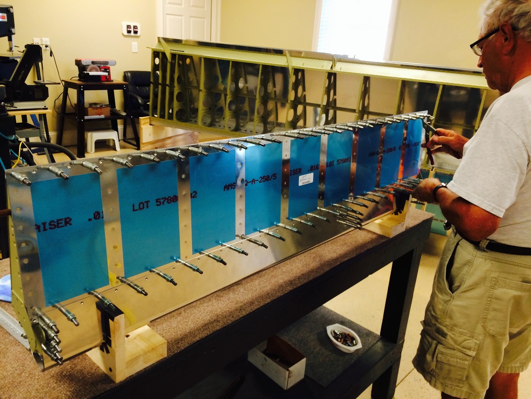
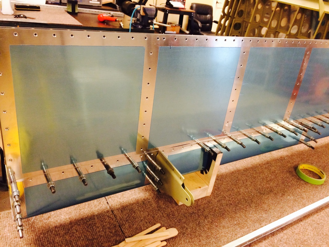
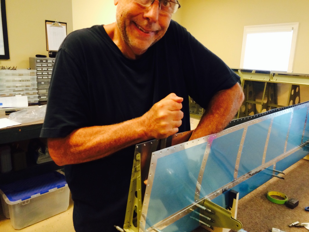
Flaps in the jig to rivet, have to make sure they are straight at this point or you may rivet in a twist.
Flap trailing edges were done with the VHB tape on the flaps rather then JB Weld. It really did not work that well. It seemed the adhesive was too thin the adhere to the V wedge. Since VHB is all adhesive with no backing, I may try 2 layers on the ailerons and see if that works better. That being said, I squeezed the trailing edge slowly alternating from the middle out and finished with the 10-11 degree head in the hand squeezer. The results were OK and the trailing edge is straight within a 1-2mm.
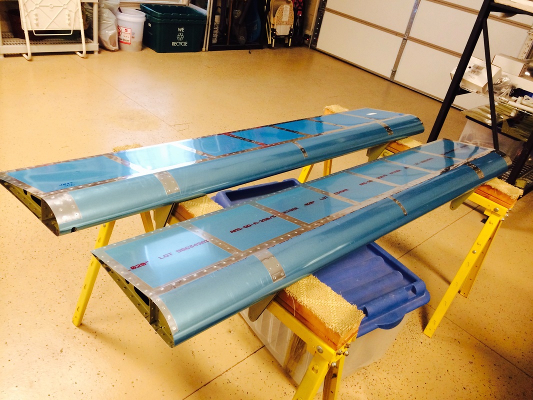
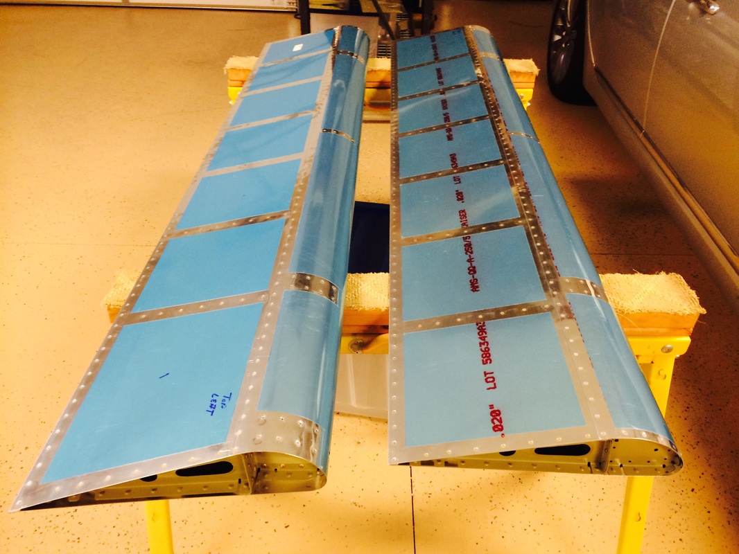
Flaps are done and are flat and straight.
