Cowl Baffle - Sec. 47
Rafael started on the baffle set which is part of the finishing kit. We talked Van's into sending it out ahead of the kit to keep him busy. Although there is still much to do with the fiberglass work, it is not always practical to double team it. Some sections are just better handled by one of us.
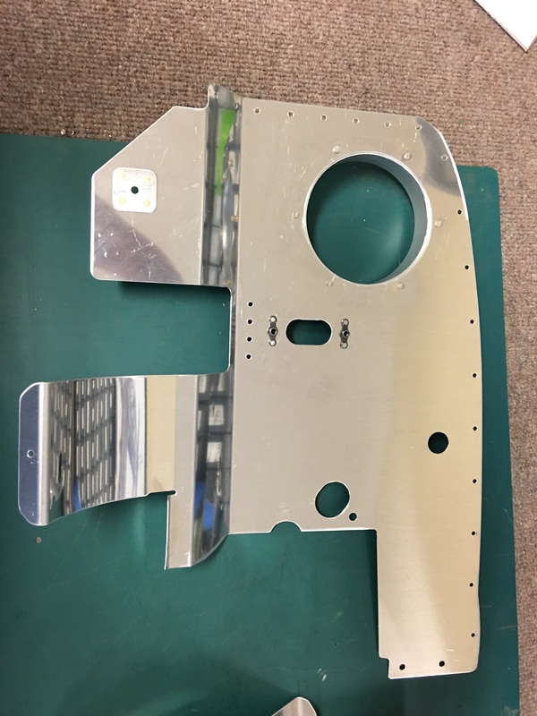
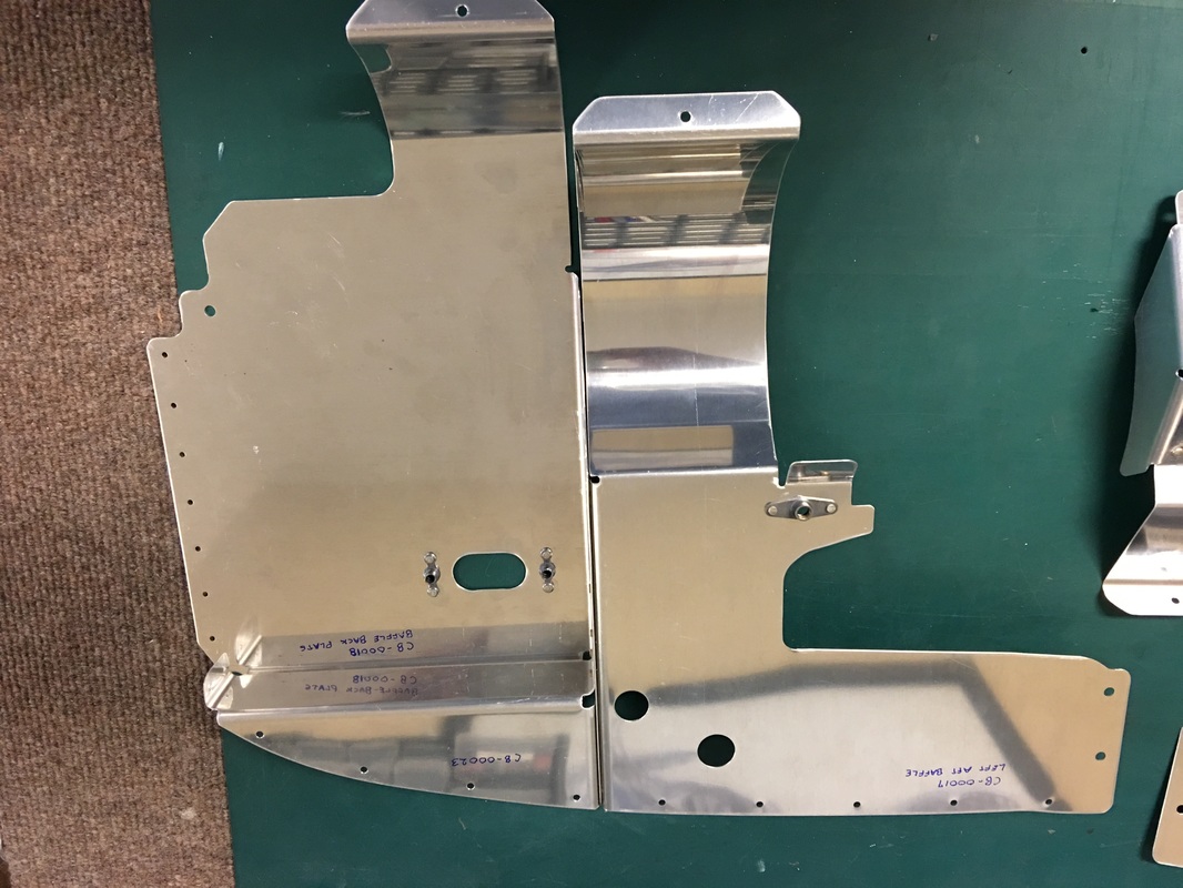
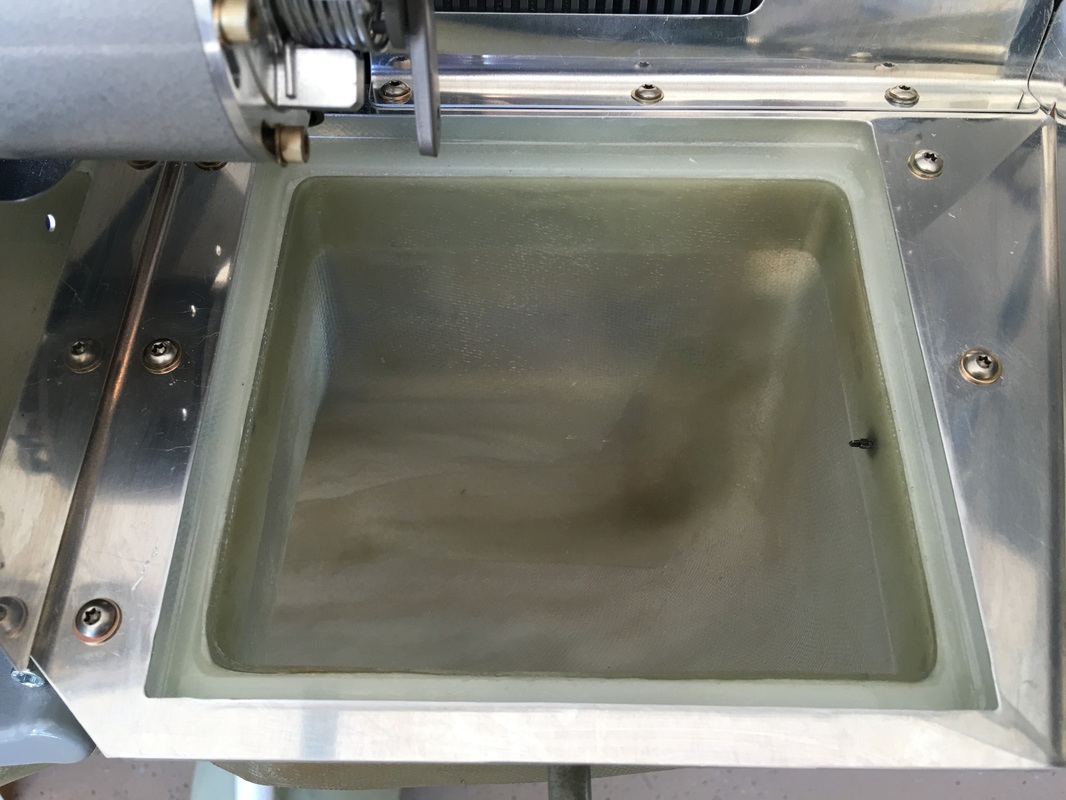
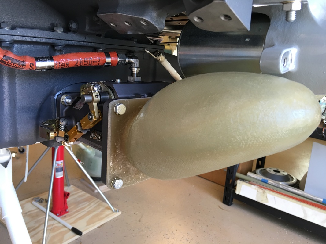
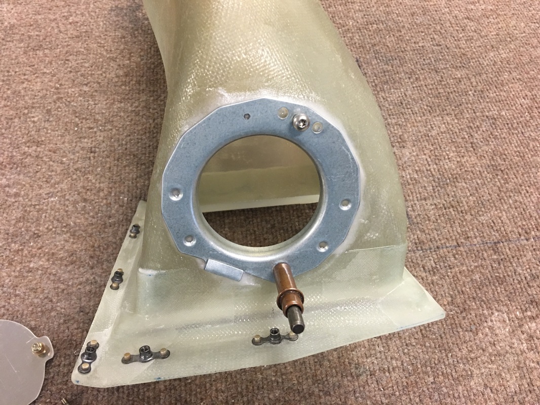
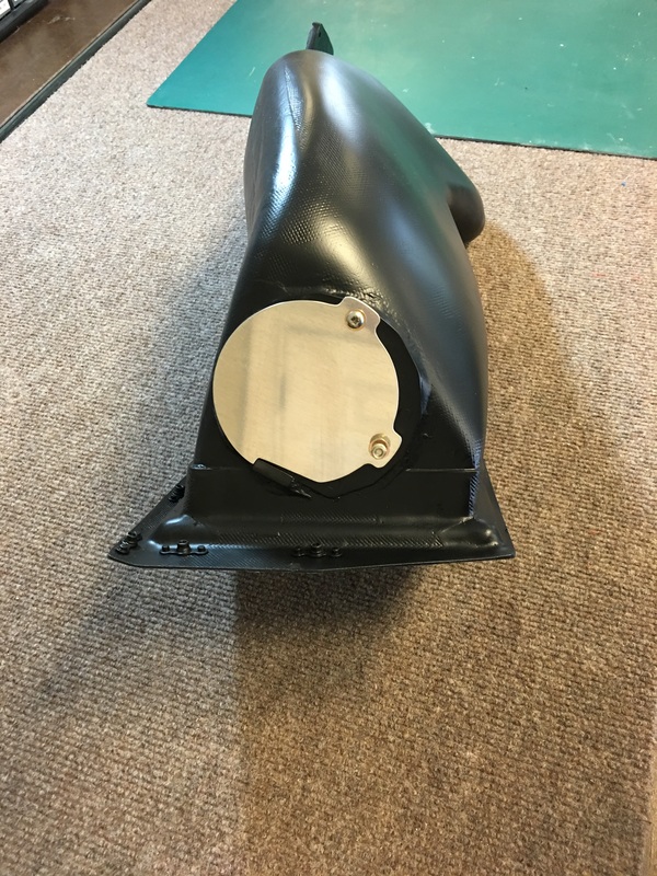
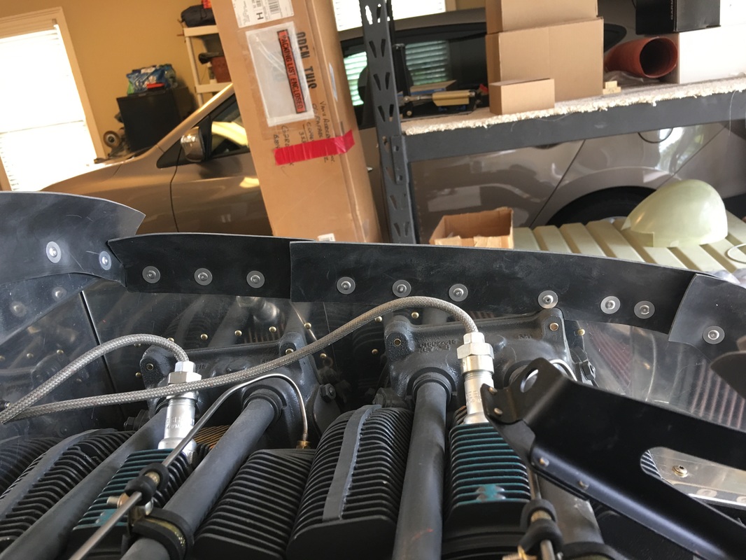
The first 3 pictures here and the back Sec. of the IO 390 baffle. The large hole is the outlet for the oil cooler which is remotely mounted on the motor mount. The older style mounted behind the #4 cylinder, but this lead to some cracking of the baffle after time. This looks like a better solution, the cooler is larger and I understand the engine is running cooler because of it.

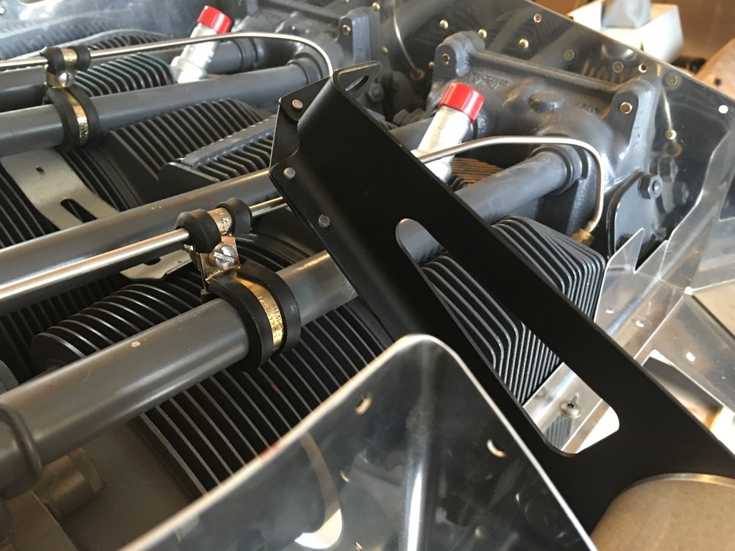

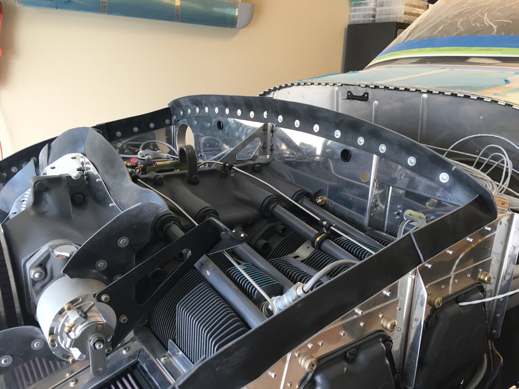
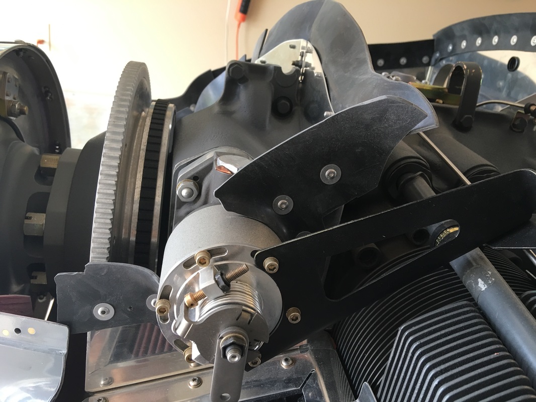
This is all the aluminum baffle frame piece installed. We are going to hold off on the rubber gap fillers until the cowl is fitted to the plane.

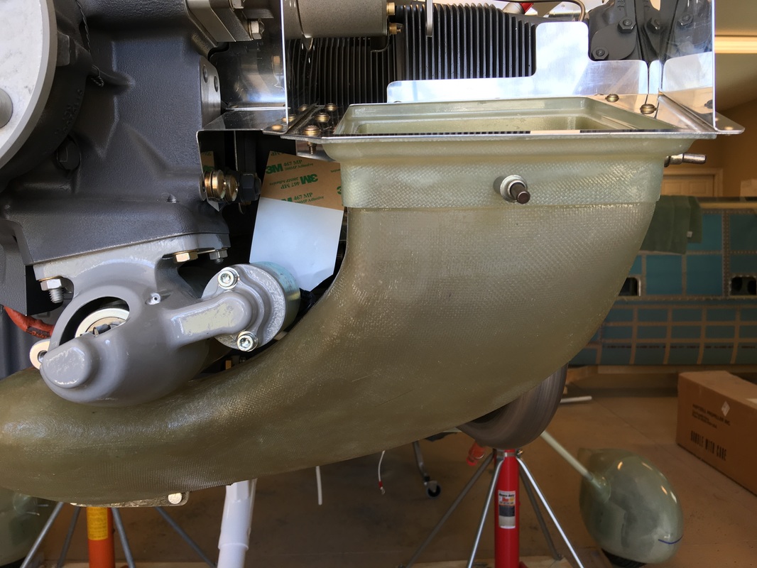
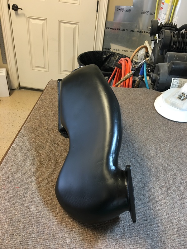
We mounted the throttle body on the engine to star work on the induction air box and filter snorkel.
Getting fiberglass parts to fit is one of the tricker issues build and RV airplane. After working with metal pieces the match up perfectly the fiberglass parts have to be persuaded to fit in almost every case. This is true of the wheel fairings, the cowl and especially this snorkel. The snorkel required considerable fitting because it goes between 2 fixed points. First the throttle body, where the venturi's must line up and then the filter frame in the baffle. This was a tough part and I spent many hours on it to get it right. A lot of tweaking, sanding and fitting is required and finally bond ing the frame to the snorkel where I deviated from instructions and did it right is place on the engine.

|
|

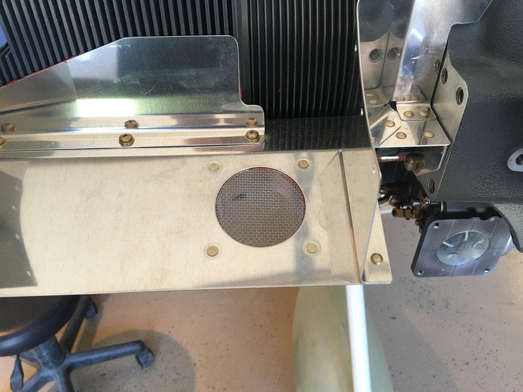
This is the alternate air inlet frame and cover plate. The plate pulls back and open the inlet with a cable incase the filter fills up with ice or debris.
The rubber cowl seal fit pretty good right out of the kit. Had a few problems with the washer/pop rivet combo, where the stem would break off in the wrong place, but other than that, all went well.
I tried the fit of the top cowl and it went on ok. I think once it is in place for a while and the heat forms the seal, it will be a very nice fit.

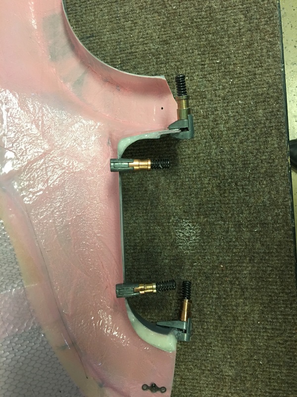
As part of the baffling installation, some special shaping of the cowl inlets is required. Van's solution is a build up some epoxy/flox at the two outside edges of the inlets and shaping them after they harden. They use the metal strips that end up holding the rubber seal to mold the flox. After waxing the metal strip and shaping them, I filled the spaces as show in the plans and let it harden. The next few pictures so the process of construction and shaping.
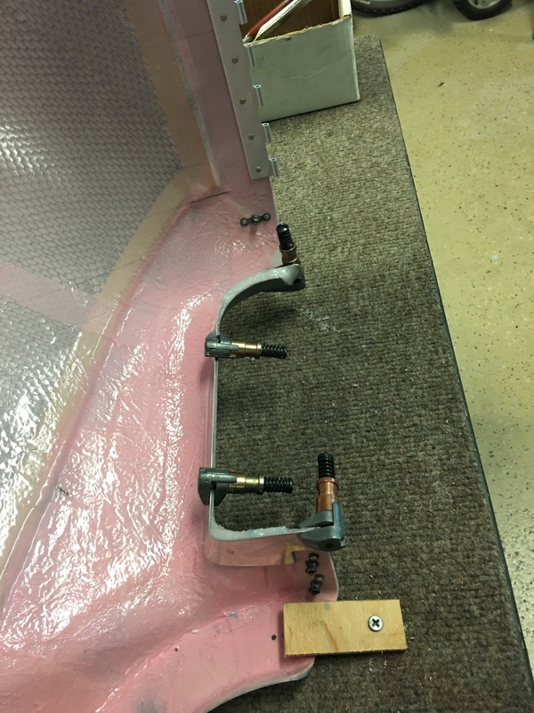
Metal strips used as the flox molds
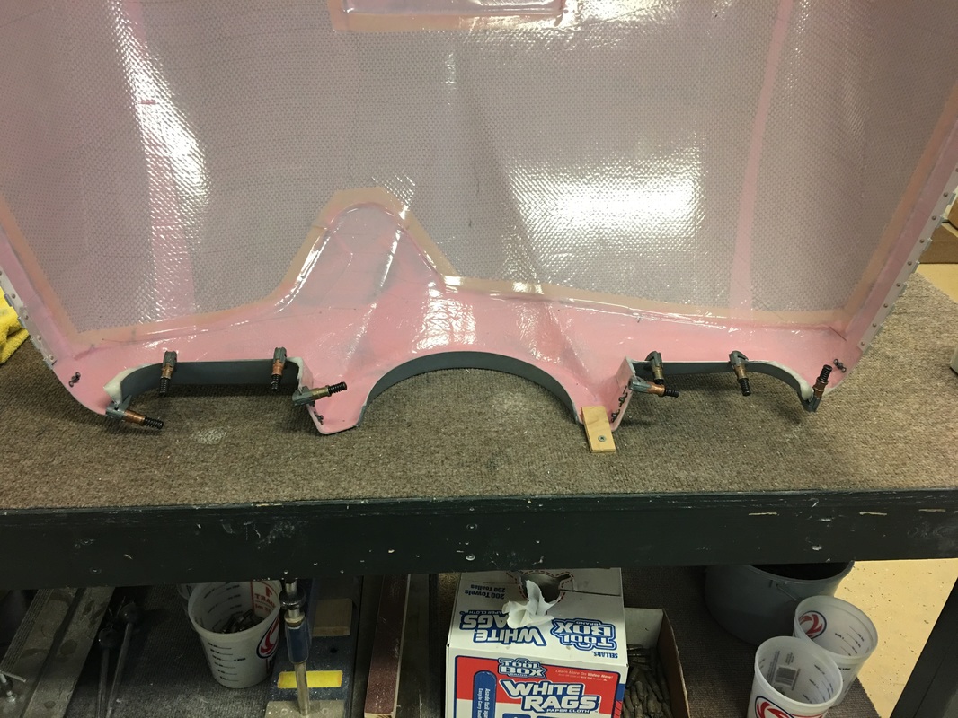

Bottom cowl after some shaping


This is the top cowl filets that still need shaping to the bottom, stay tuned.
