Forward Mid Fuselage Side Structure - Section 29
These are the drag fittings right out of the kit, real quality abounds in the kit parts.
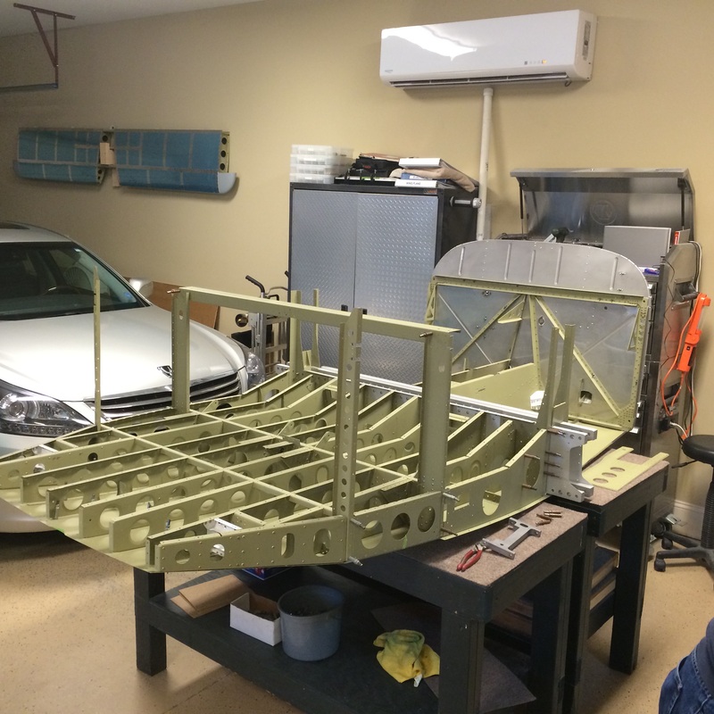
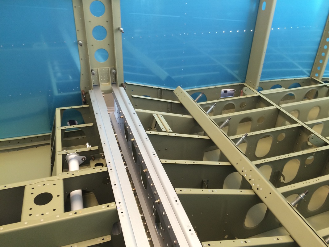
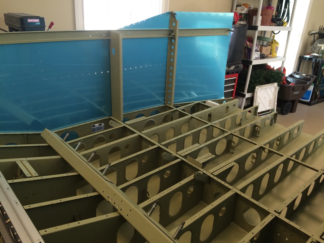
This is where you slide the seat section over the front section and start the process of joining the them together
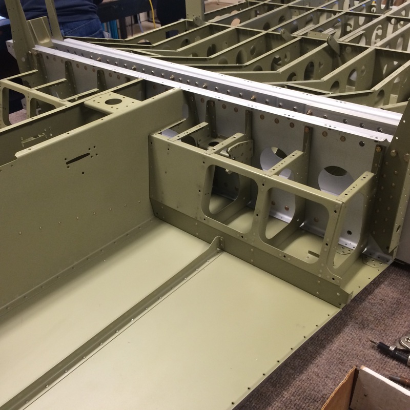
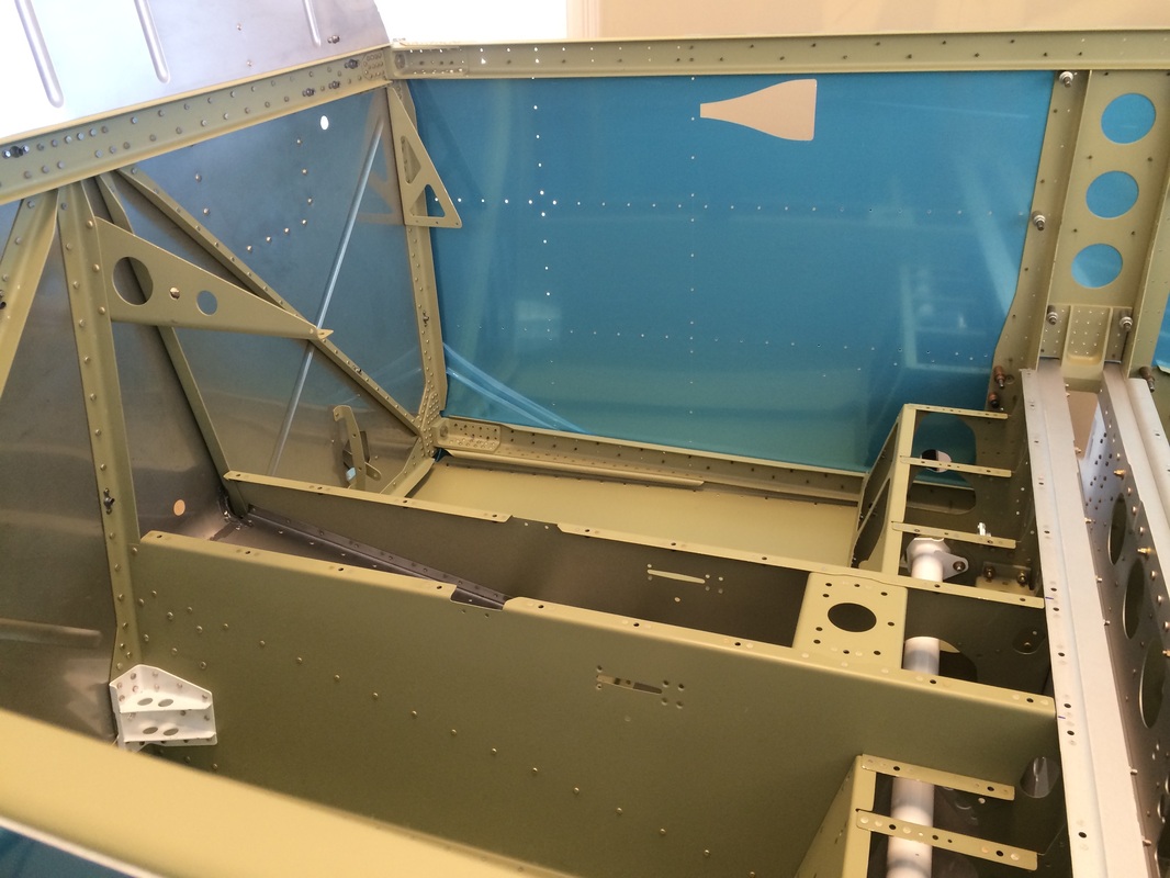
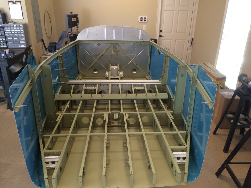
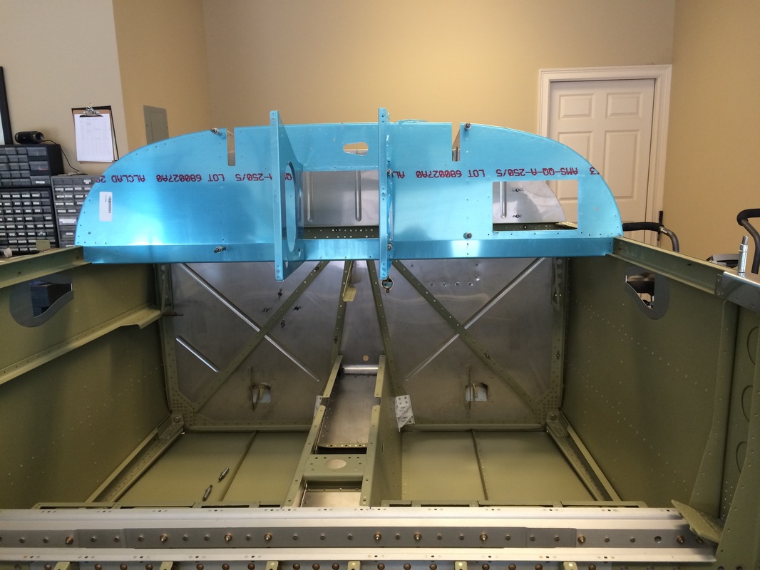
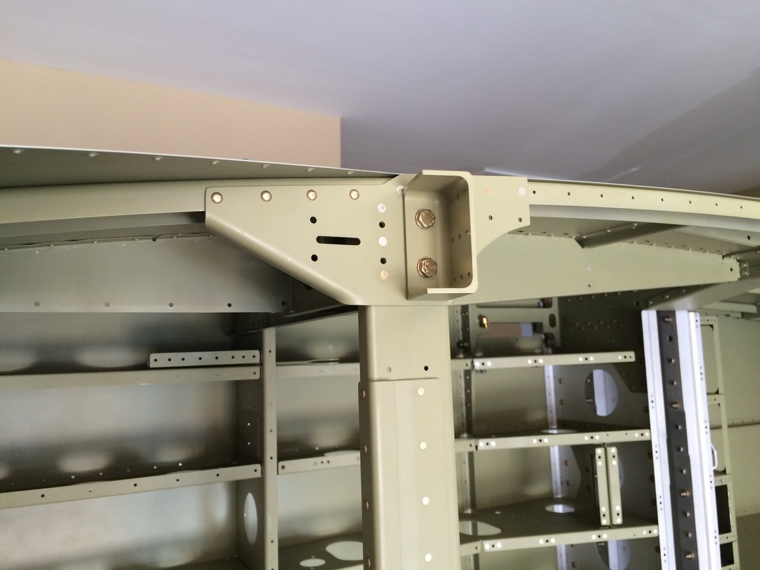
This view is from the front fuselage section after joining it to the seat / baggage section.
The upper and lower drag fittings after priming being clecoed for match drilling
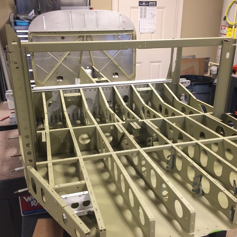
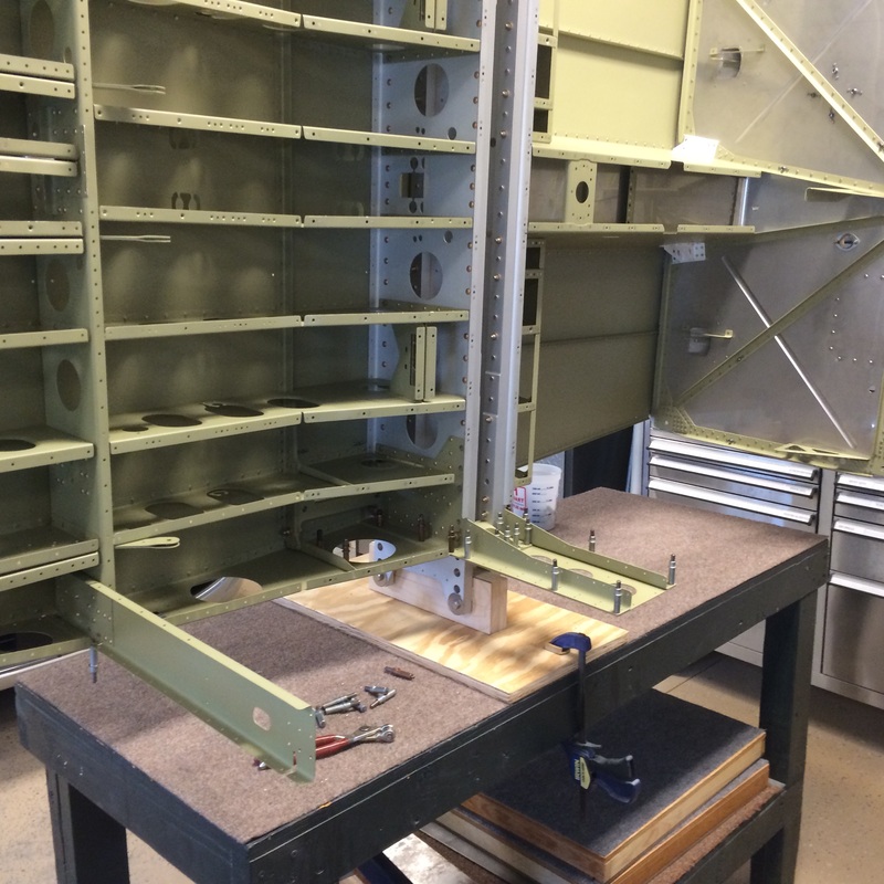
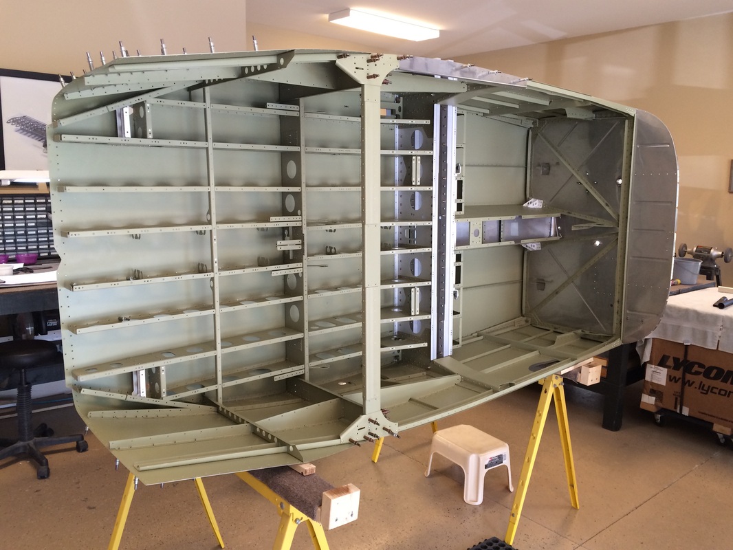
Overview shot of the two sections being joined together soon to be tipped onto the side for riveting
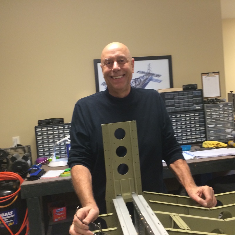
Me, getting ready to match drill the upper drag fitting
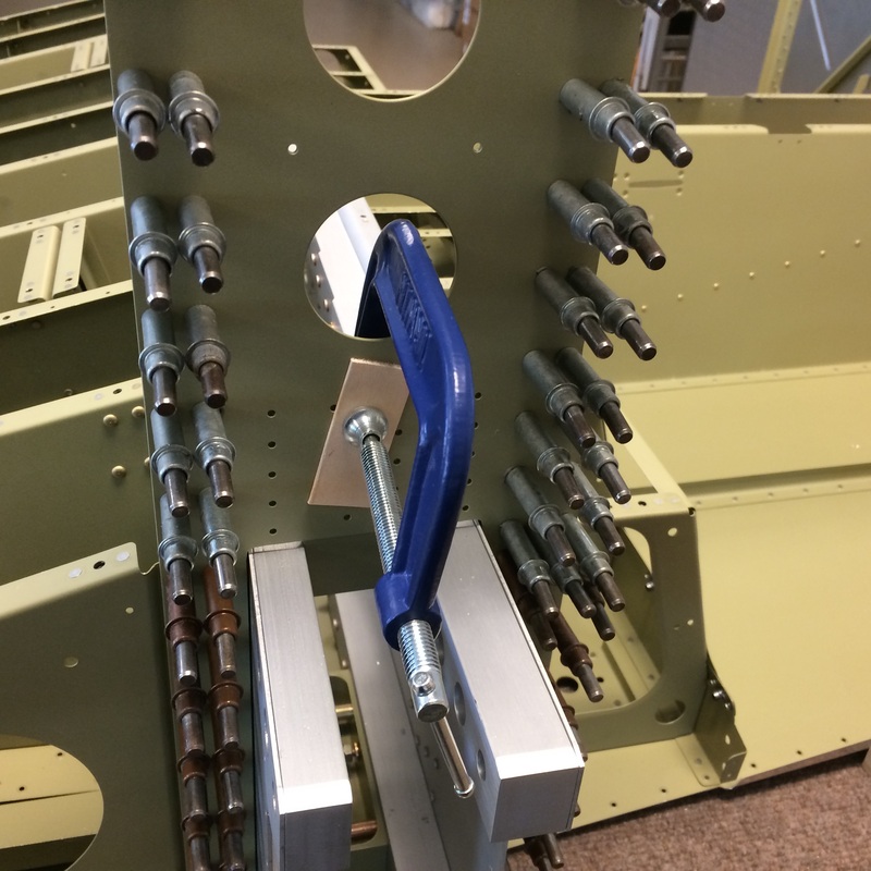
Clamped and clecoed in place per the instructions being prepped for match drilling drag fitting

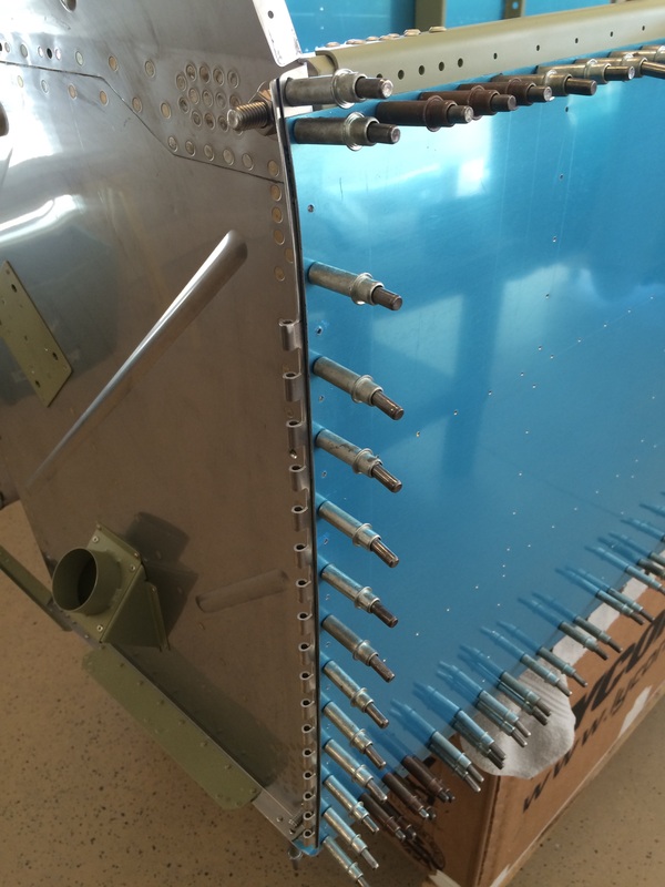
Here is the match drilling process of the drag fitting, I drilled the first hole with a 90 degree block and clecoed. Then I use the cleco's as a guide to keep the 6" drill perpendicular to the fitting.
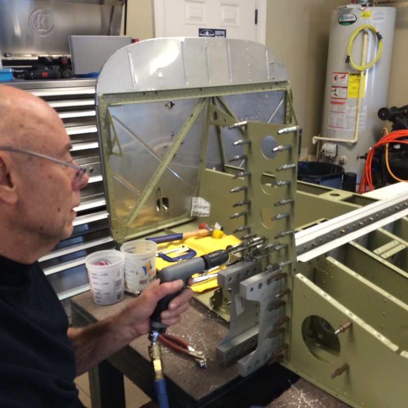
Another shot of drilling the drag fittings
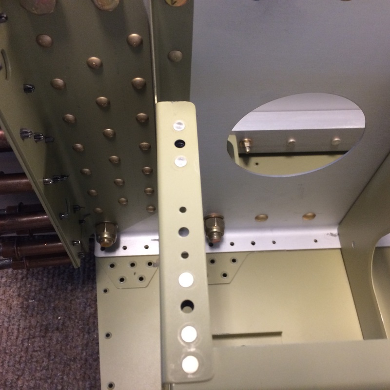
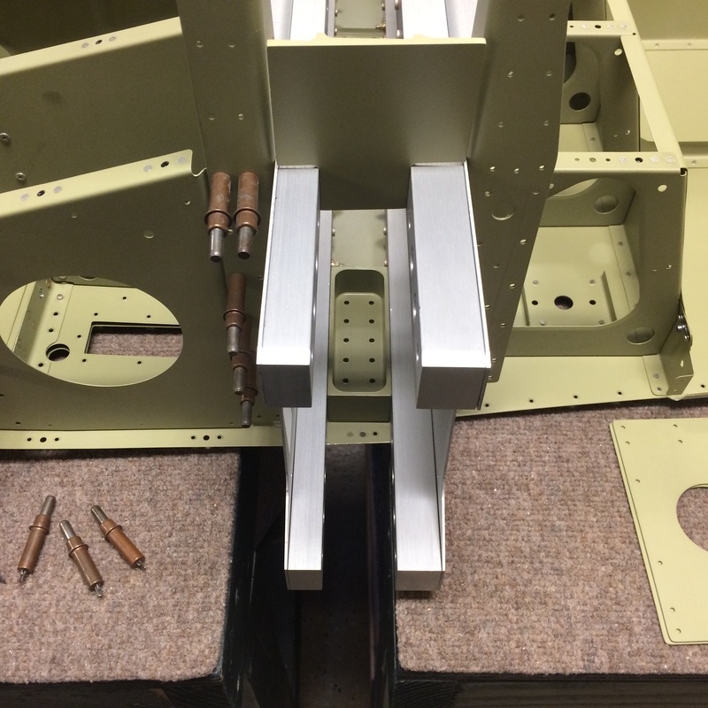
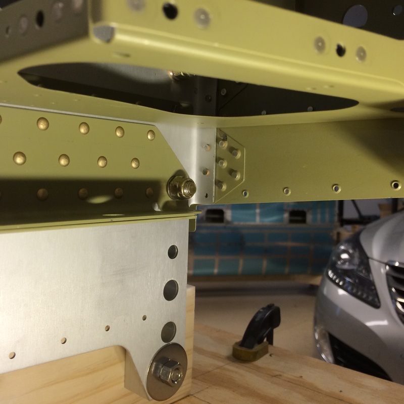
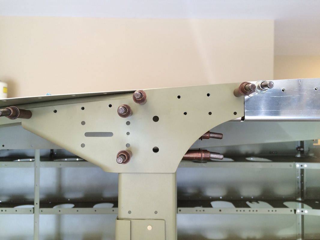
Two 3/8" bolts in place holding the bottom drag fitting tightly in place for match drilling
This is the landing gear mount bolted in place with the bottom drag fitting, they will come out to rivet the bottom skin to the drag fitting, spars, bulkheads, and overlapping skins
The fuselage bottom is now on it's side so we can rivet with good access and view. This works out well since the spar bolted the to the fixture is at the center of gravity. We clamped it to the bench and started riveting.
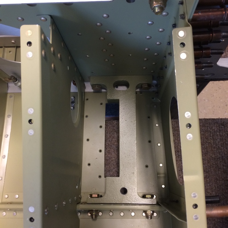
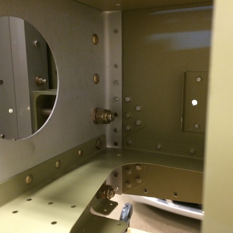
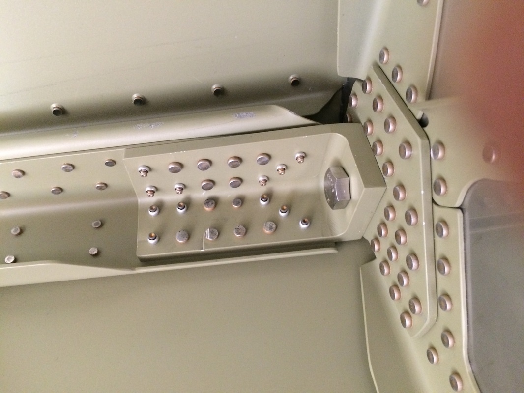
Bottom drag fitting after bolting and riveting, this area is very strong as it should be since this is where the wings and landing gear attach
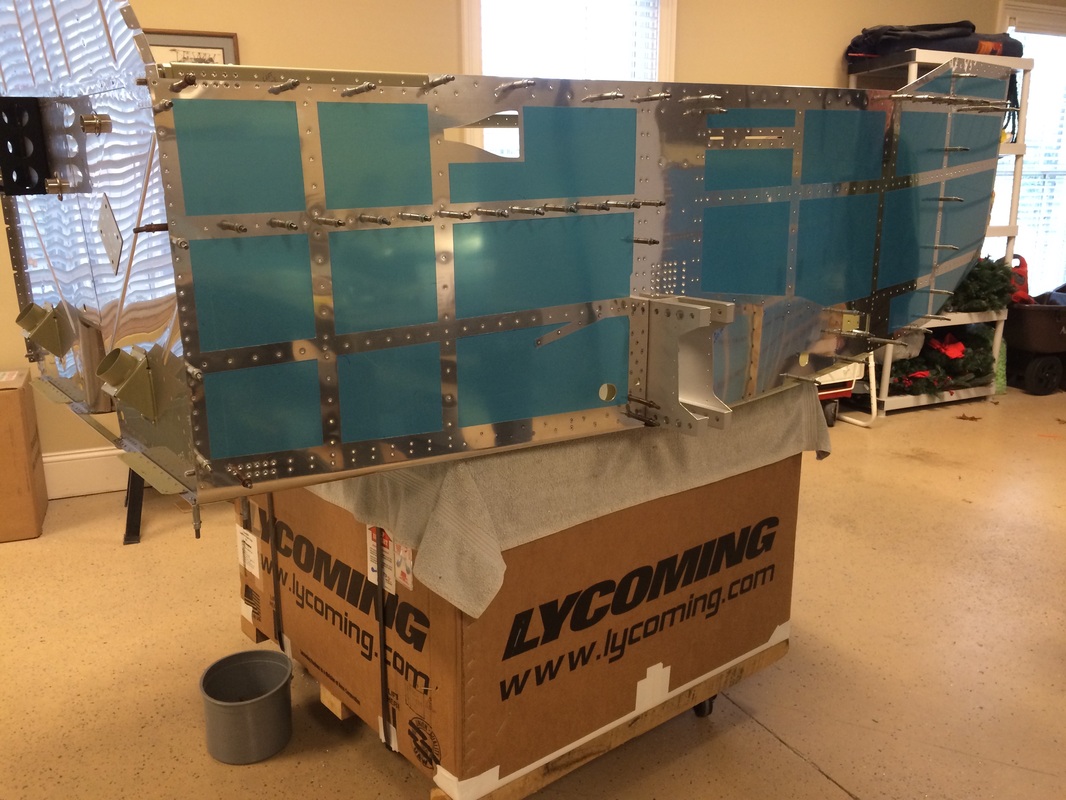
This is a good view of the all the rivets in this area, The large button head rivets are 5/32" Cherry CR's, the only rivets on the bottom that are not flush, and require a strong and to pull.
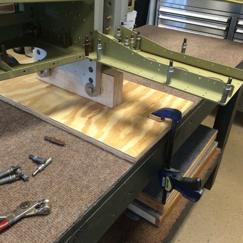
A close up of the fixture for holding the fuselage vertical for bottom riveting. The dimensions are in the plans except for the base plate. We used a 3/4" x 24" x 12' piece of ply and screwed with (4) 3 1/2" screws
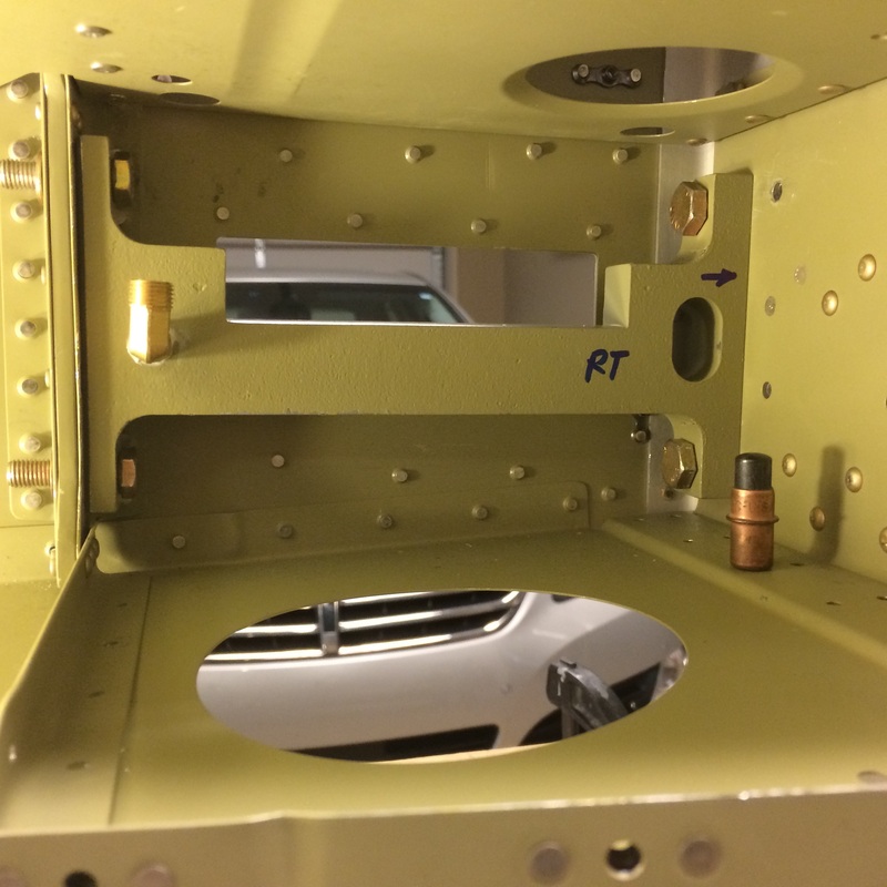
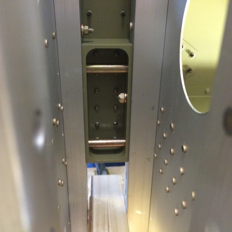
Gear mount with brake line fitting installed, note the rivets are installed below the landing gear mount. It has to come out to finish the riveting.
Bottom assembly has been turned to finish riveting the other half where the cleco's are.
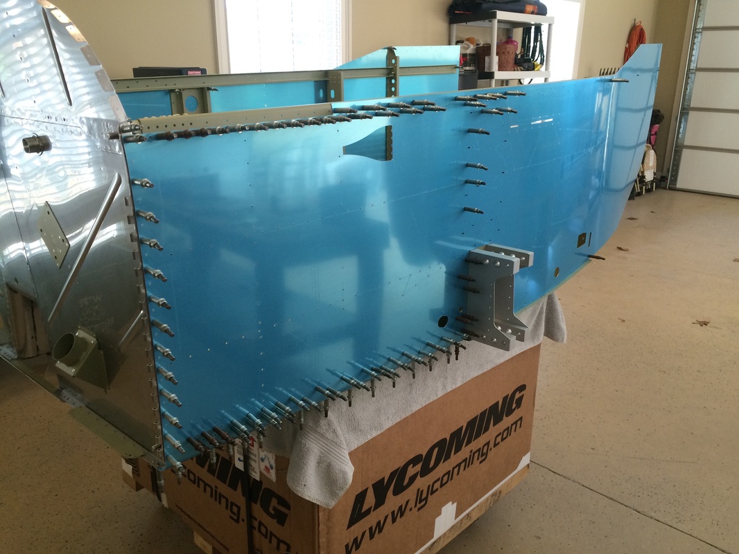
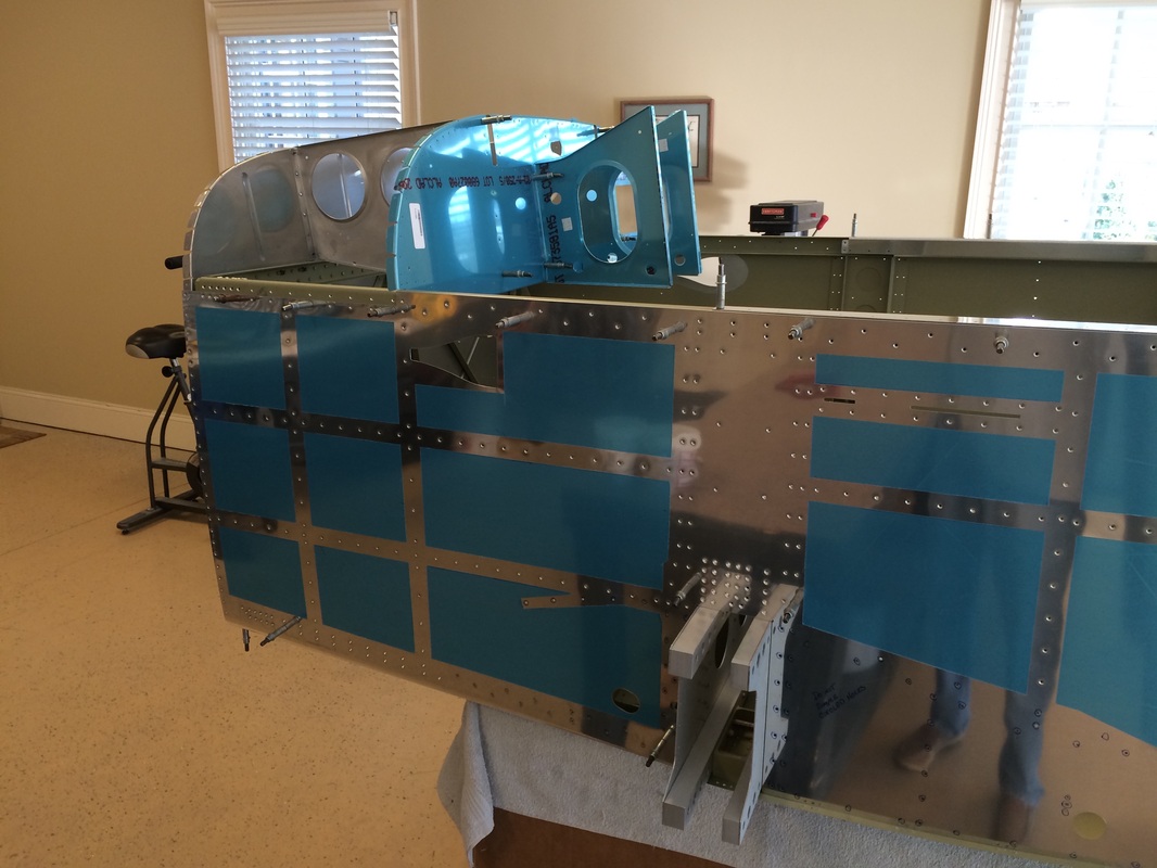
We installed the longerons and side skins today with some difficulty. I found the top one need a little more twist and by starting at the 4 corners of the skin we got better alignment and the cleco's while snug went into any hole we tried.
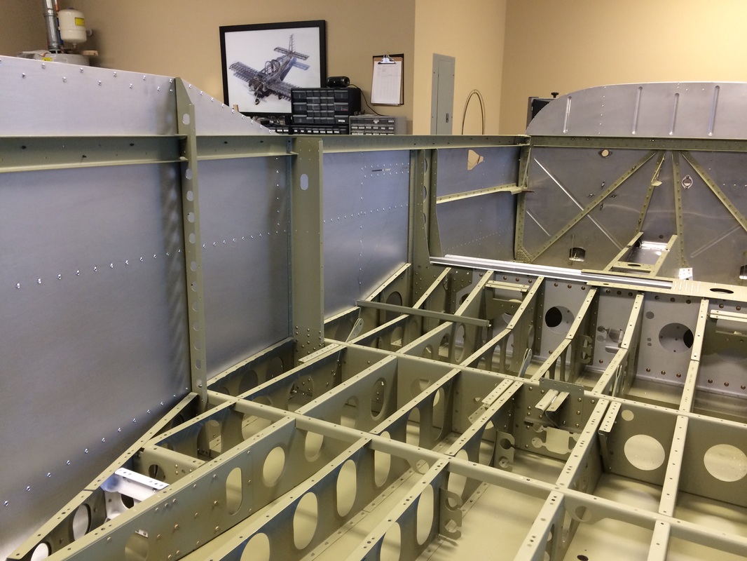
Nice big roomy interior and stout construction shows here.
Trimming and installing the hinges for the cowl was more difficult then I though they needed to be. I did get some movement of the shim during the process on the first hinge and change the process from the plans slightly for the second one. I started with the hole shown in the plans and used side clamps every 3" or so to keep the hinge shim line in place and located behind the skin hole. This worked well.
Next step is pulling the skins and getting them dimpled for final assembly
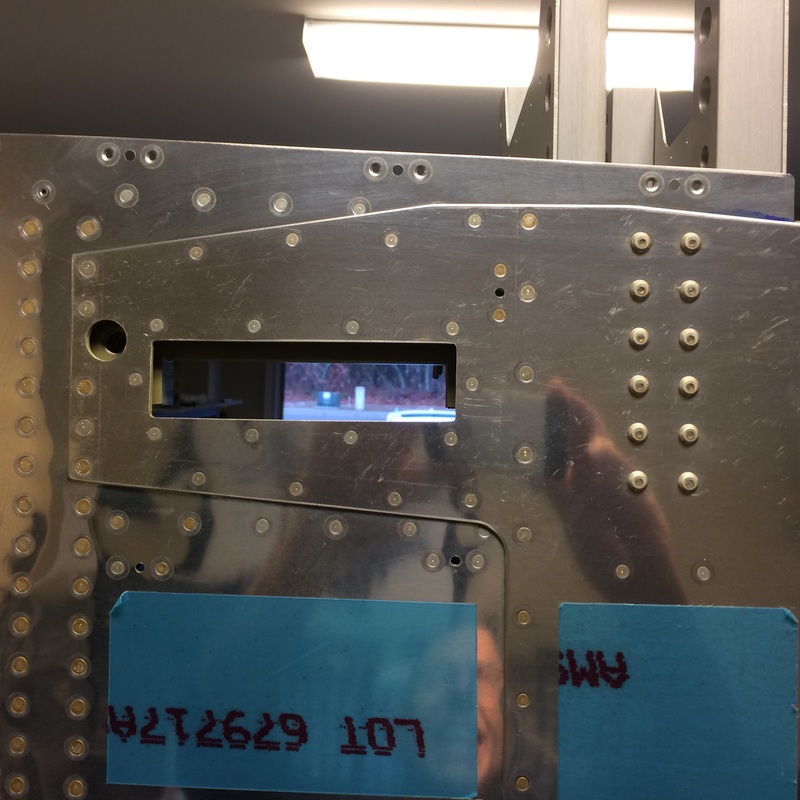
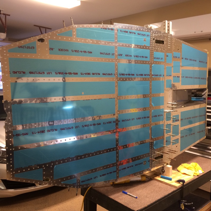
Checking holes, dimples, alignment before priming the inside of the side skins
A little different view
Inside view before priming skins to insure fit
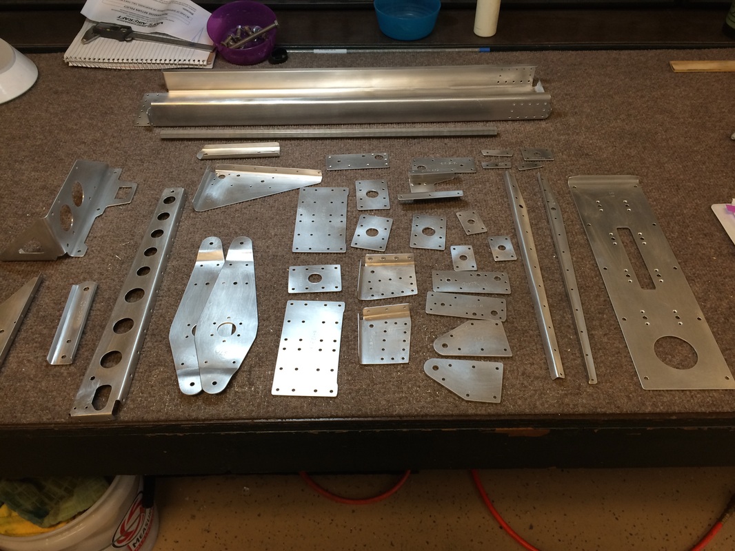
Rafael was busy making parts while I took a week trip to Florida, he is getting even next month
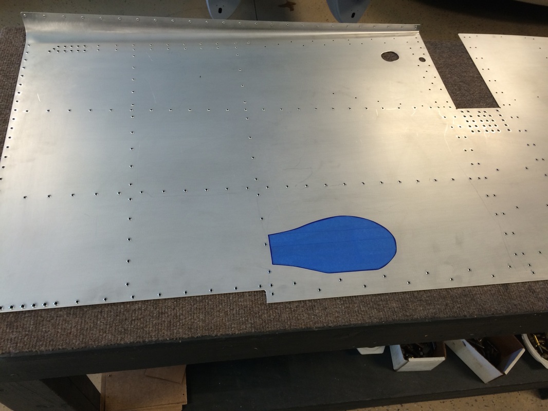
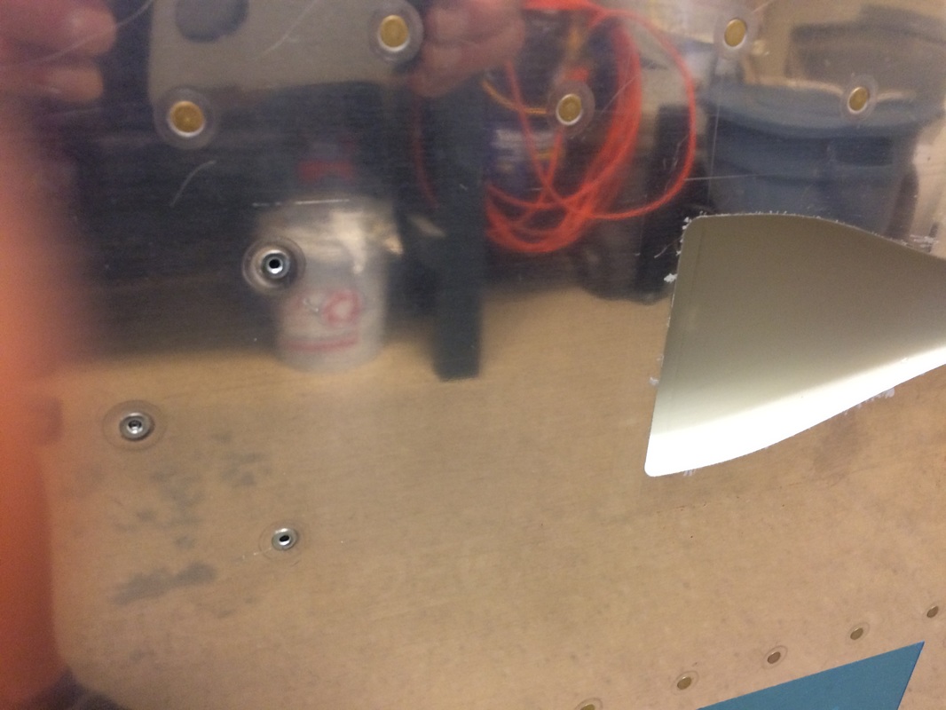
Taping off the area where the NASA duct glues to the side skin with Pro-Seal

This is the plastic vent/duct that glues to the skin
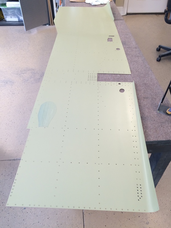
Side skin after priming with AZKO, this primer is the best! easy to spray, tough as nails and impervious to fluids, nut said.

Side skin after removing the tape for the vent
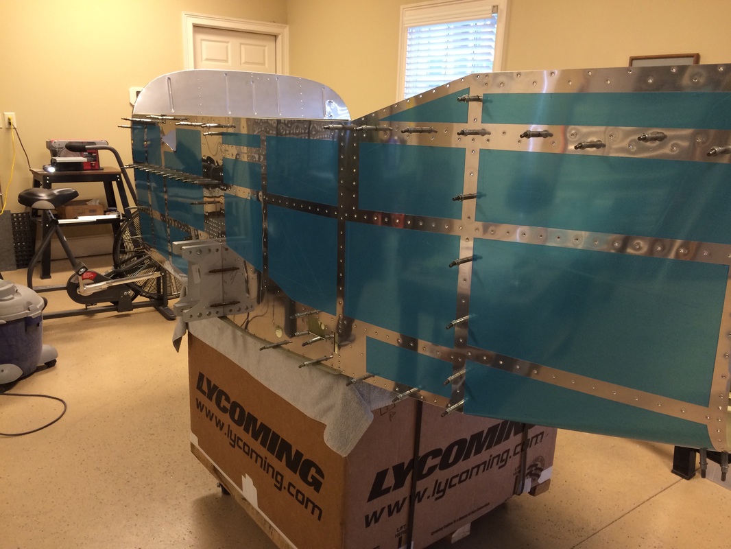
Side skins in place after priming

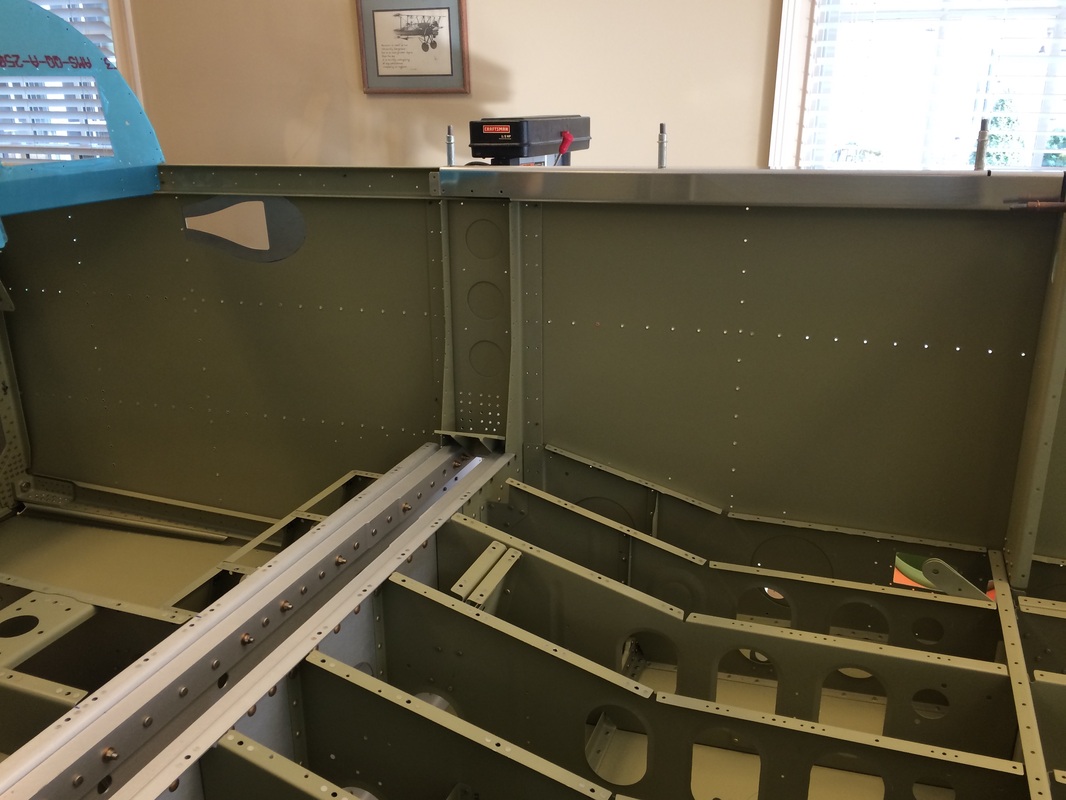
The fuselage is starting to come together, inside view before all the side framing is attached
We are starting some of the behind the panel framework
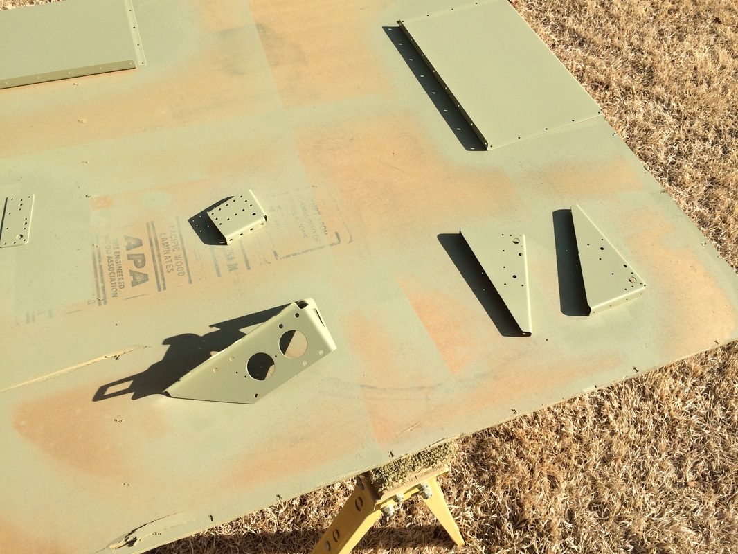
More parts getting primed

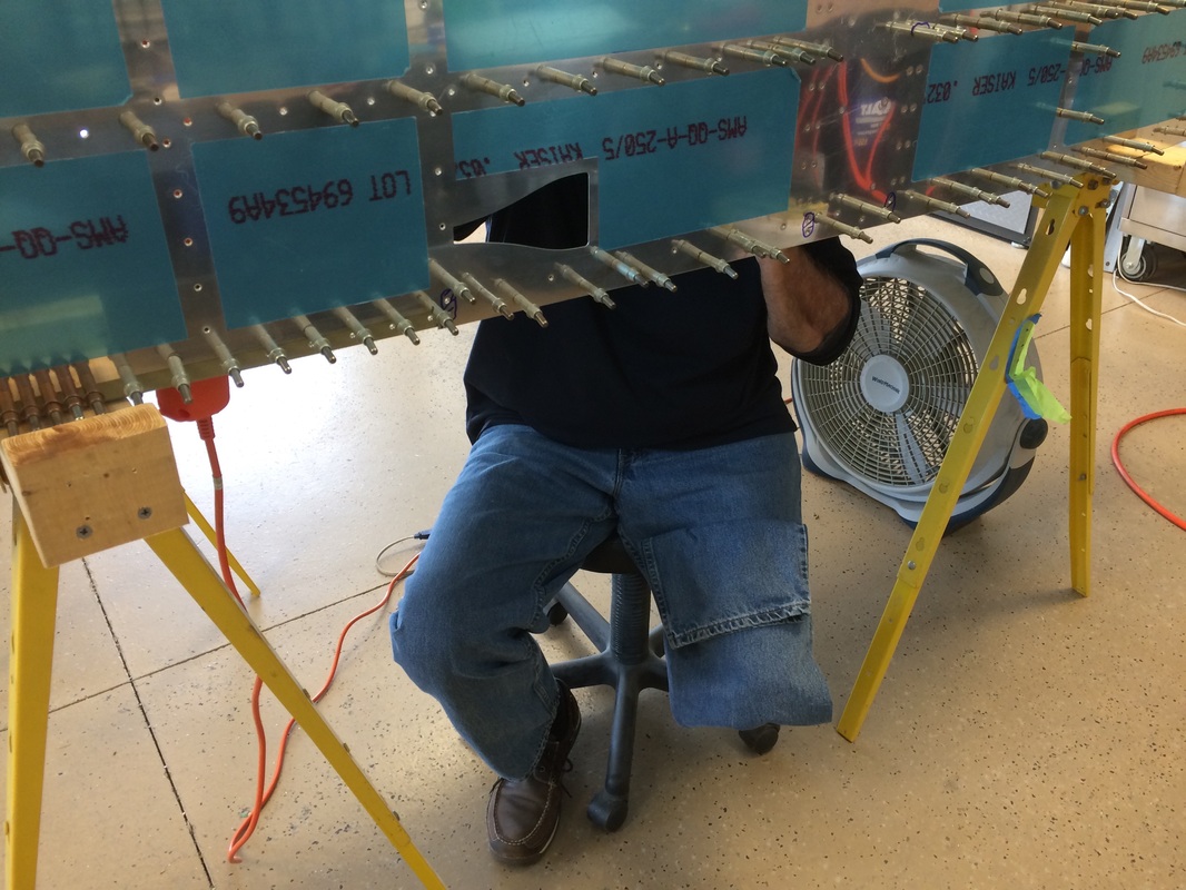
We turned the fuselage upside down on saw horses to rivet the side skins

There a lot of rivets in these side skins
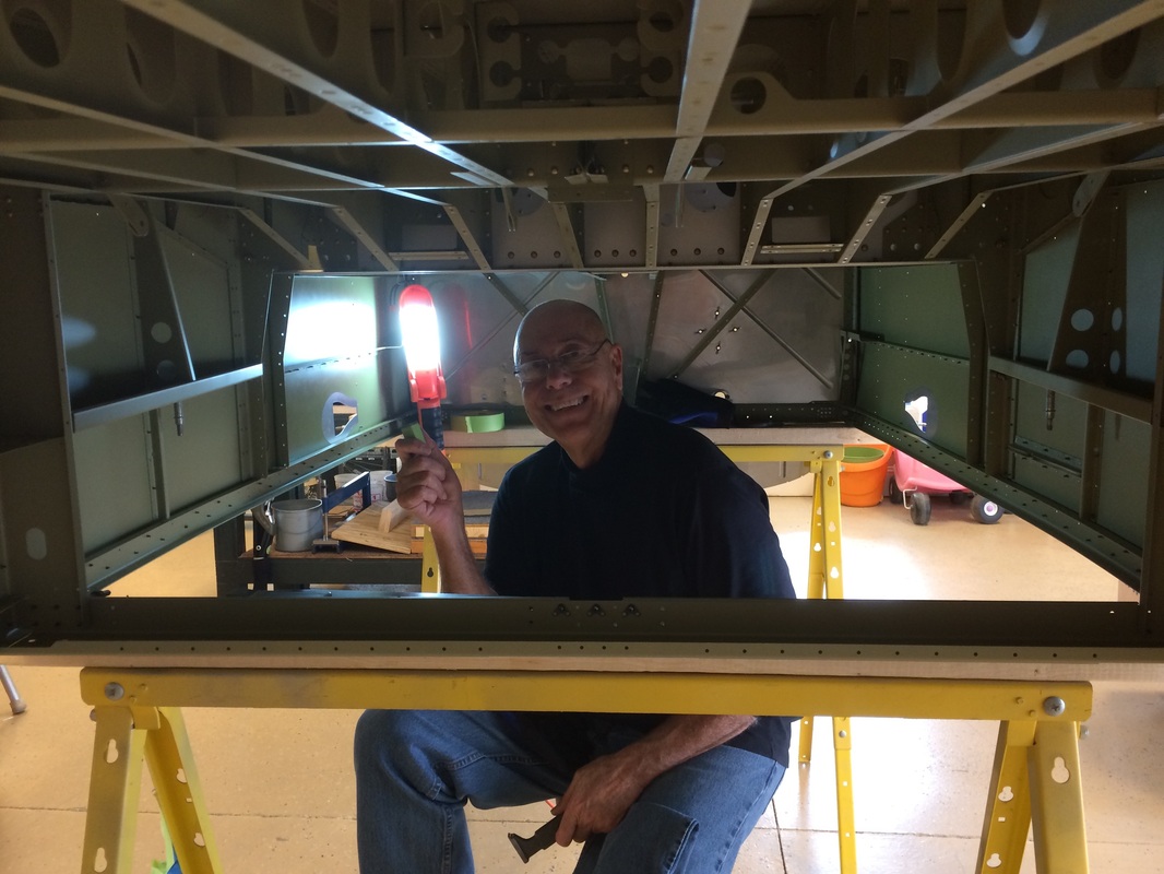
This has been my home for the last few days, bucking the rivets is the fuselage sides
This little adjustable stool keeps me at the right height for bucking. This is working out very well with good access to almost all of the the side rivets
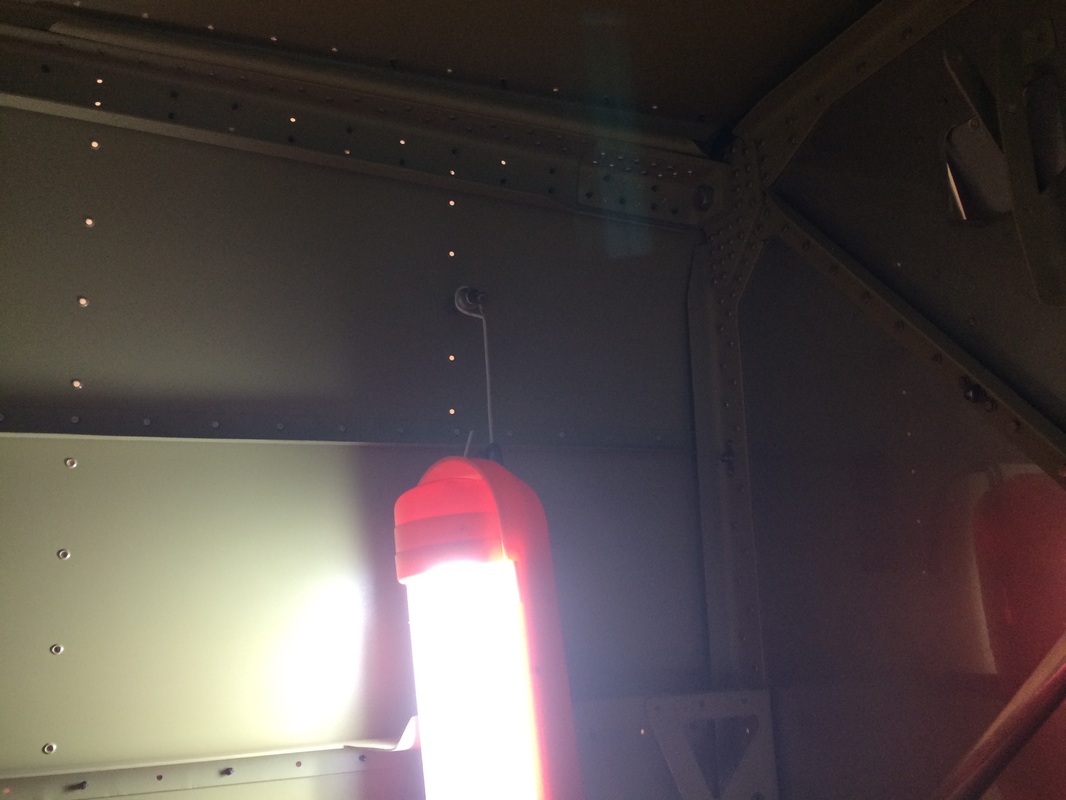
Lighting in the upside down fuselage

With a light inside this is the view I have for bucking.
Here we put the fuselage on the side to get better access to some bottom riveting
We put in the seat brace and gusset for riveting
This is the seat gusset riveted in place and the roll over citing bolted and torqued in place
Bottom motor mount looks strange with some AN rivets and some Cherry rivets, but this is the way it is supposed to be. The Cherry rivets are stronger in shear and add strength to the assembly
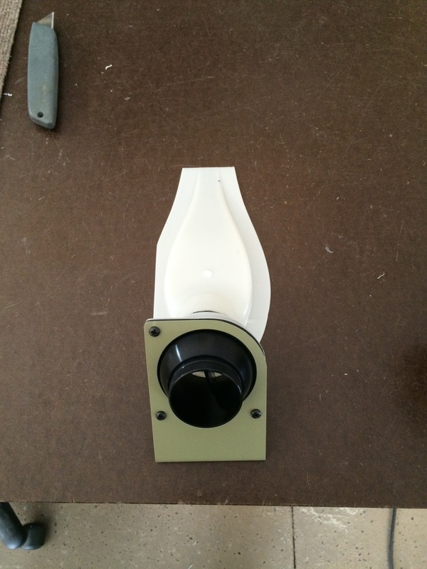
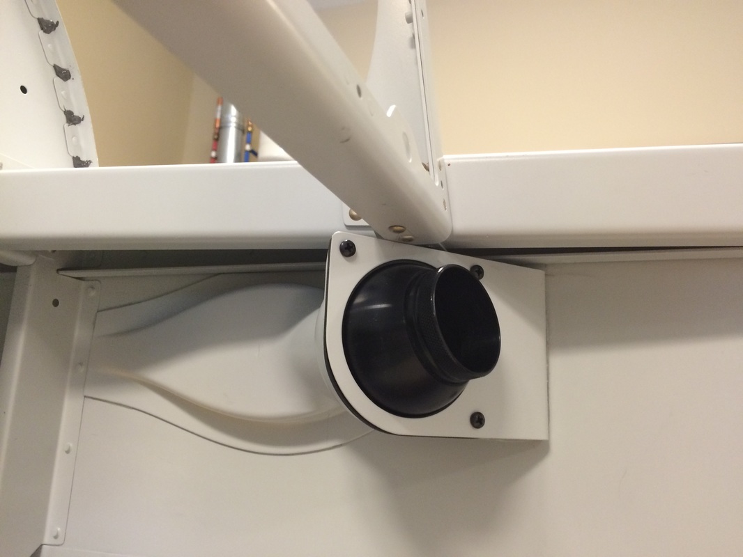
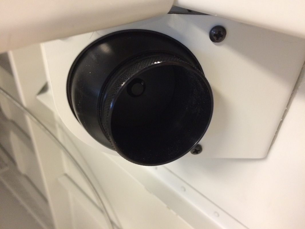
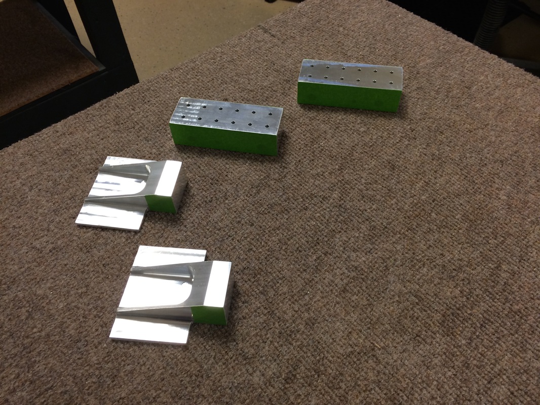
We upgraded the air outlet vents to the aluminum version to the tune of $125 each, as Van's says in the catalog, expensive but worth it. The I had to cut the corner off them. Good thing I have steady hands!!
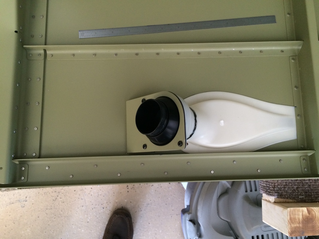
This is where the air vents go, but we did not ProSeal them in place yet. I will do this after we paint the inside.