Wing Assembly - Section 14
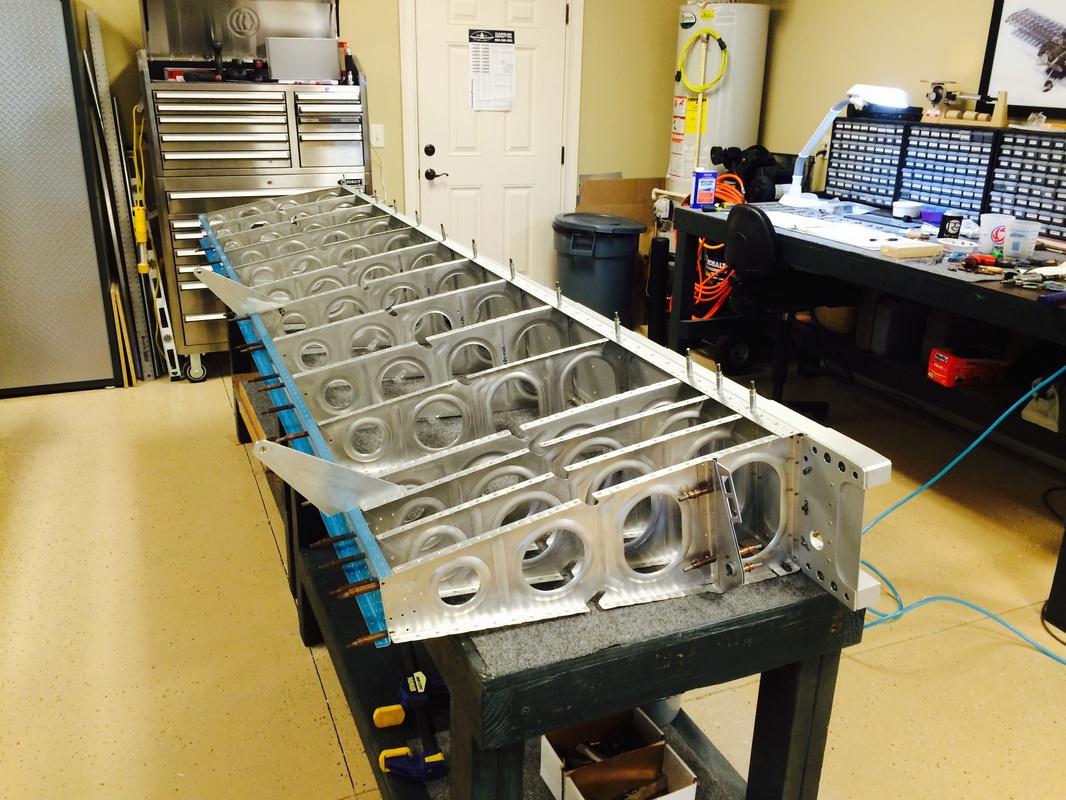
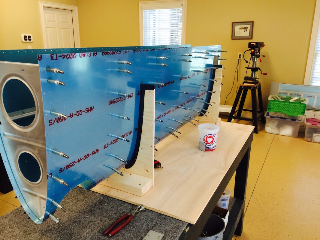
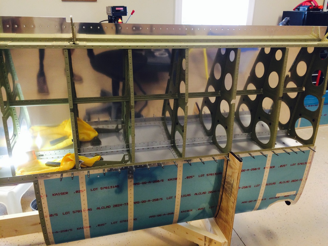
Trail fitting the rear spar with the ribs and flap brackets

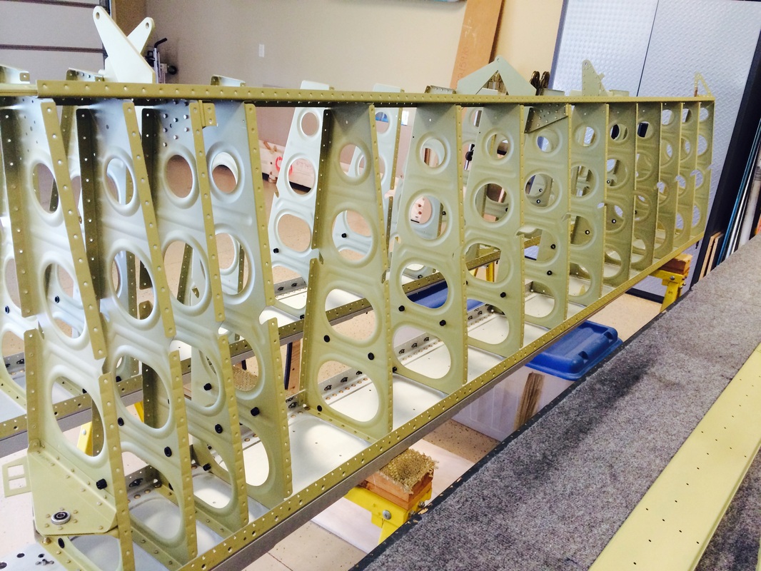
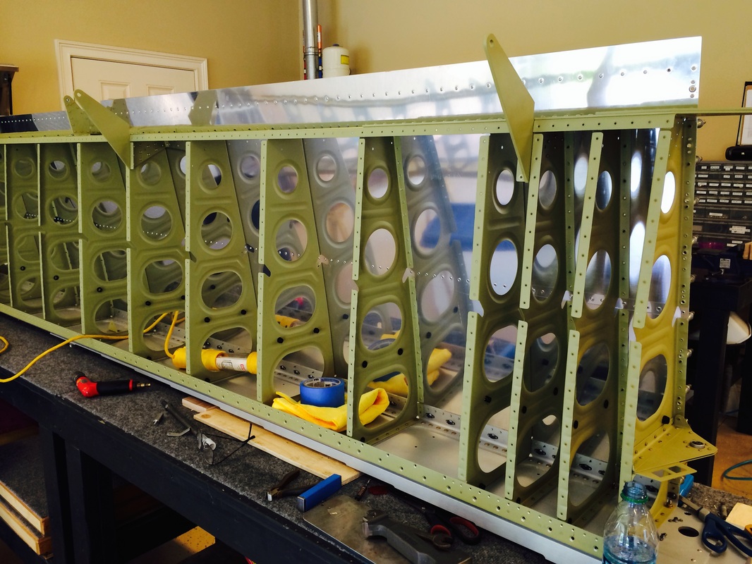
Front main spar view with the ribs and rear spar
This is where the rubber meets the road, do all the holes line up to the punched skin. Yippie the do!
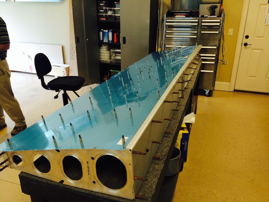
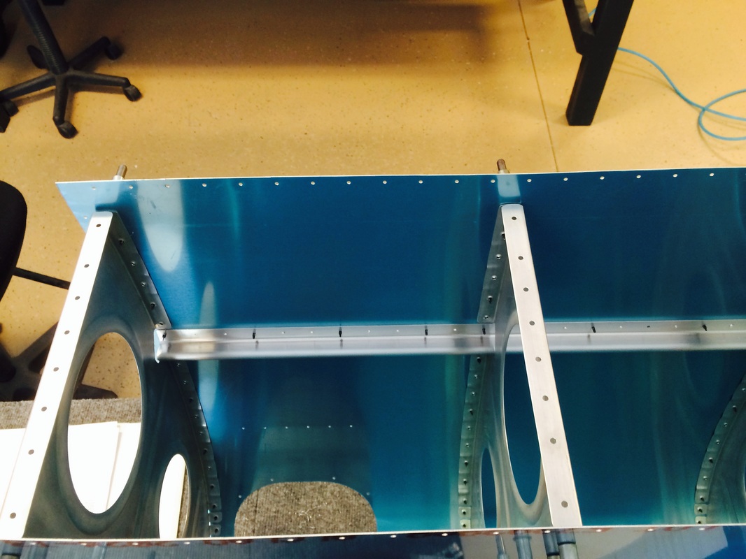
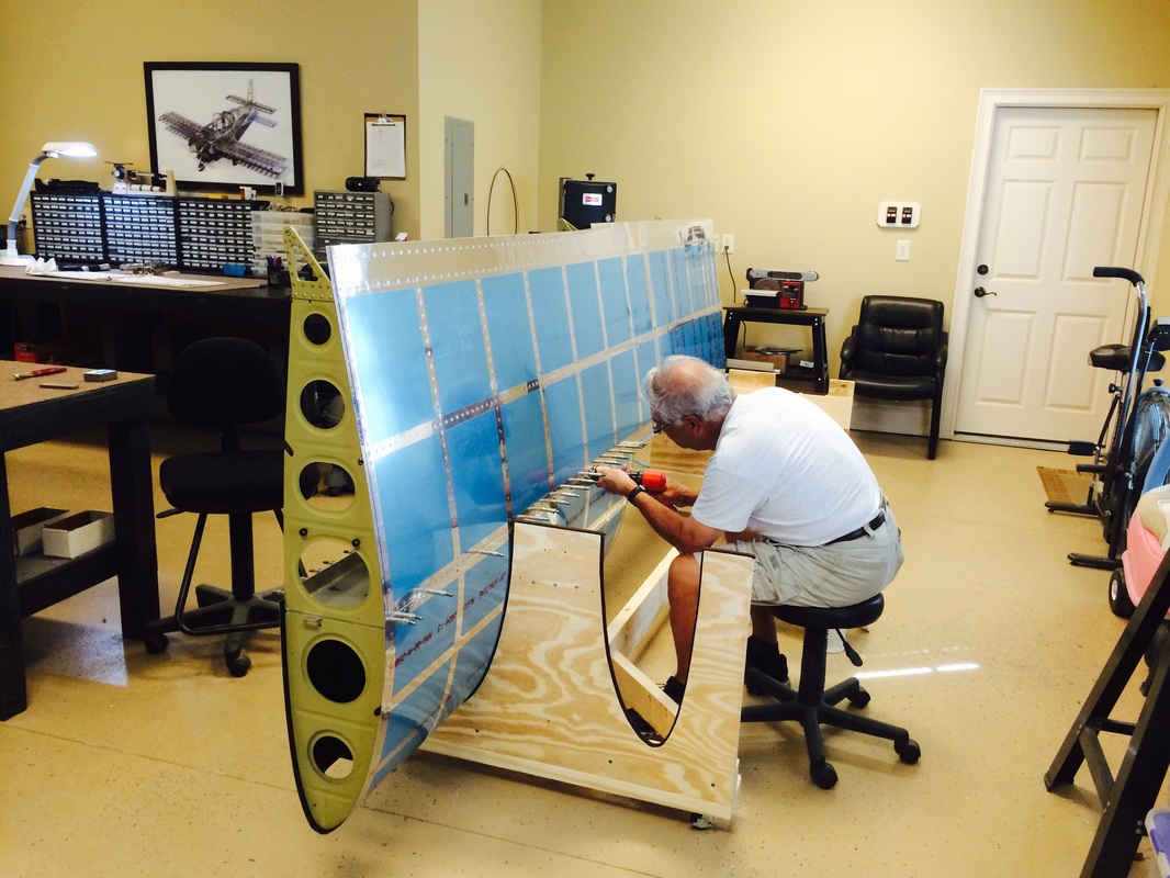
A view from the root rib of the wing.

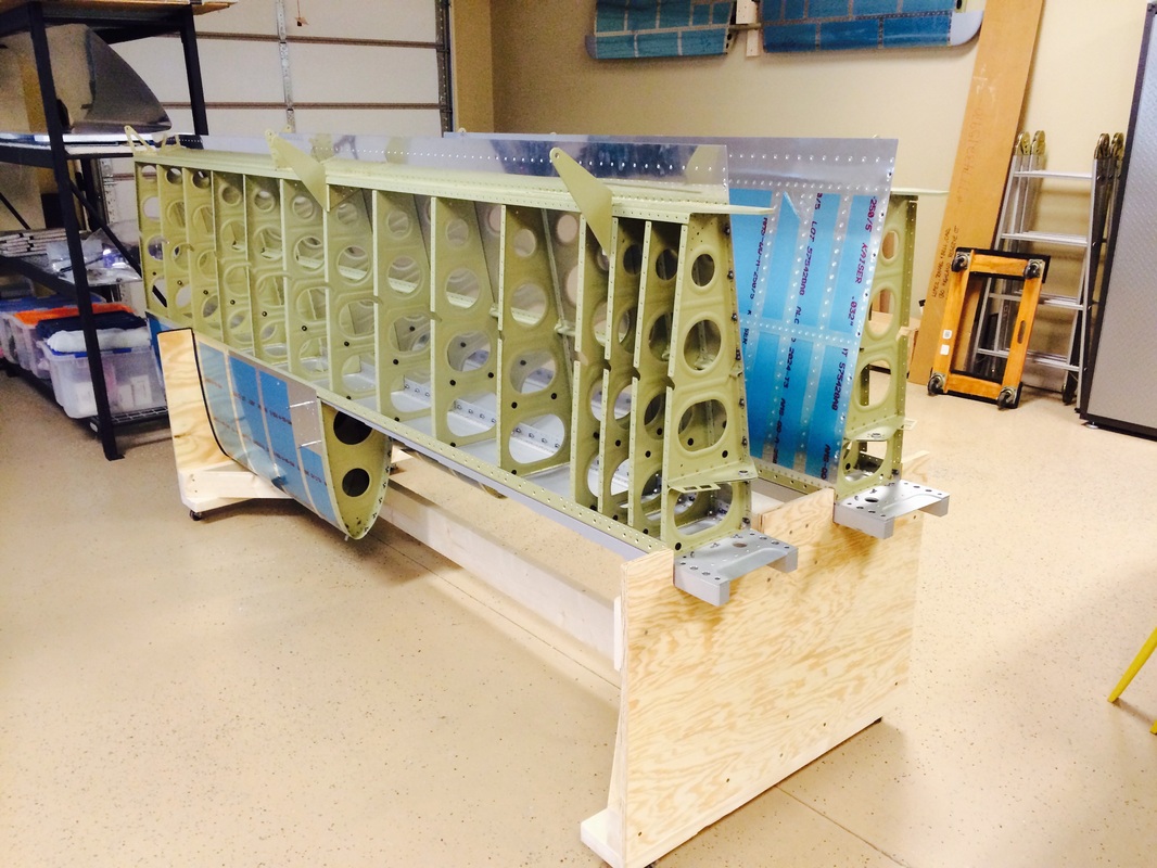
Aileron and flap brackets in clecoed in place, just checking fit here
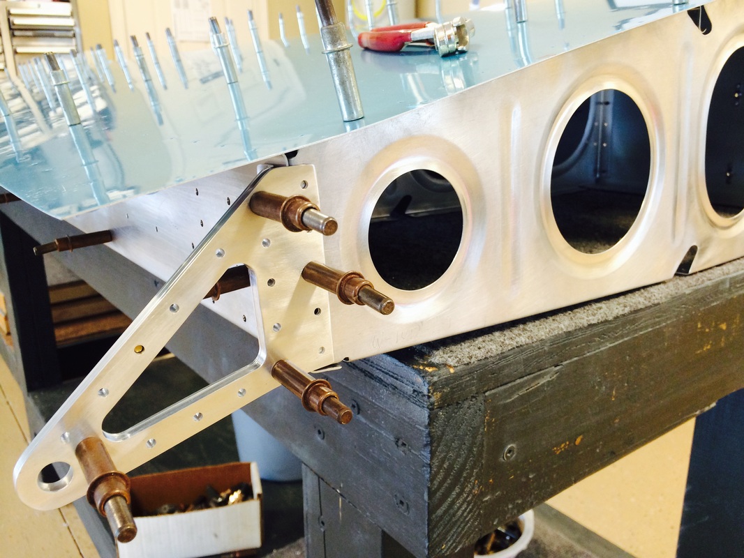
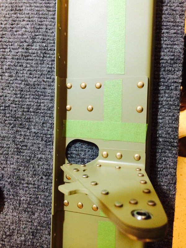
Close up of the outside aileron hinge bracket

Here you can see the holes line up for the most part, just a few slightly off that will come into place with cleco's
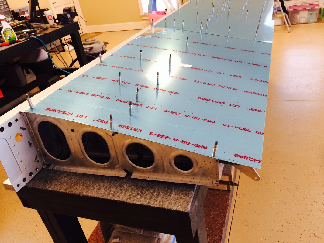
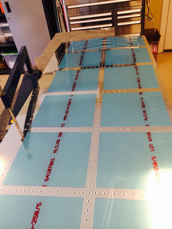
This is the start of the outboard leading edge, it requires some match drilling of the J strip and some hole on the ribs. I left the film on during this step to keep the skins from getting scratched on the inside, but it will come off soon for dimpling.
A view of the J strip which is match drilled to the strip.

This is all of the parts in this assembly clecoed together. Priming and dimpling comes next.
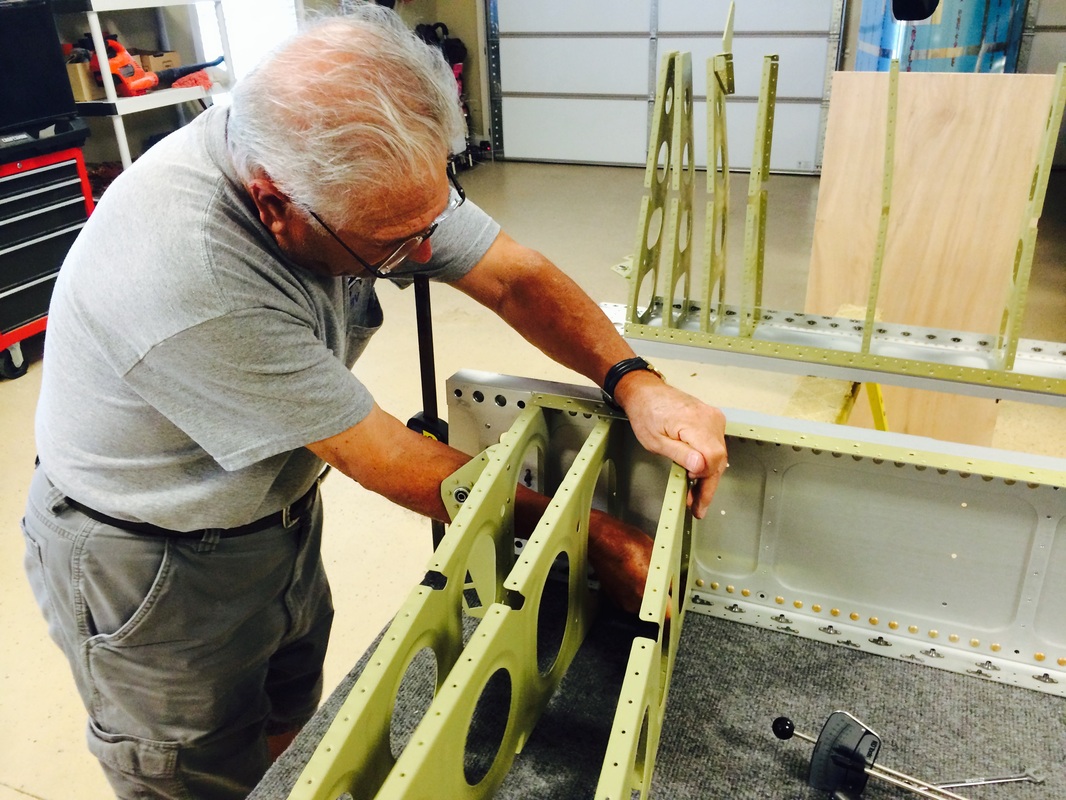
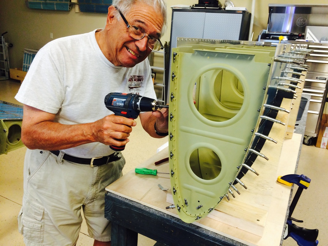
Rafael is mounting the main wing ribs with the AN 3 bolts, we will rivet the flanges next. This is the final assembly of the ribs now that they have been primed with AKZO.
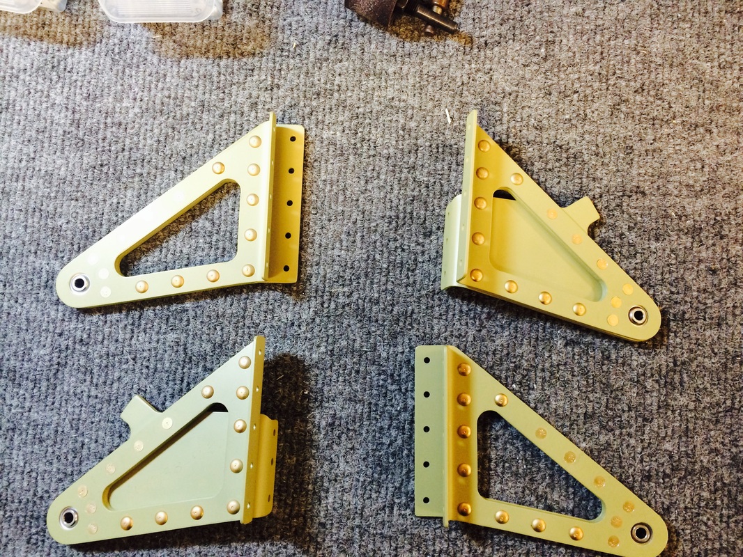
I assembled the aileron bearing brackets today, they look pretty robust and are ready to attach to the rear spar once we have attached it to the ribs.

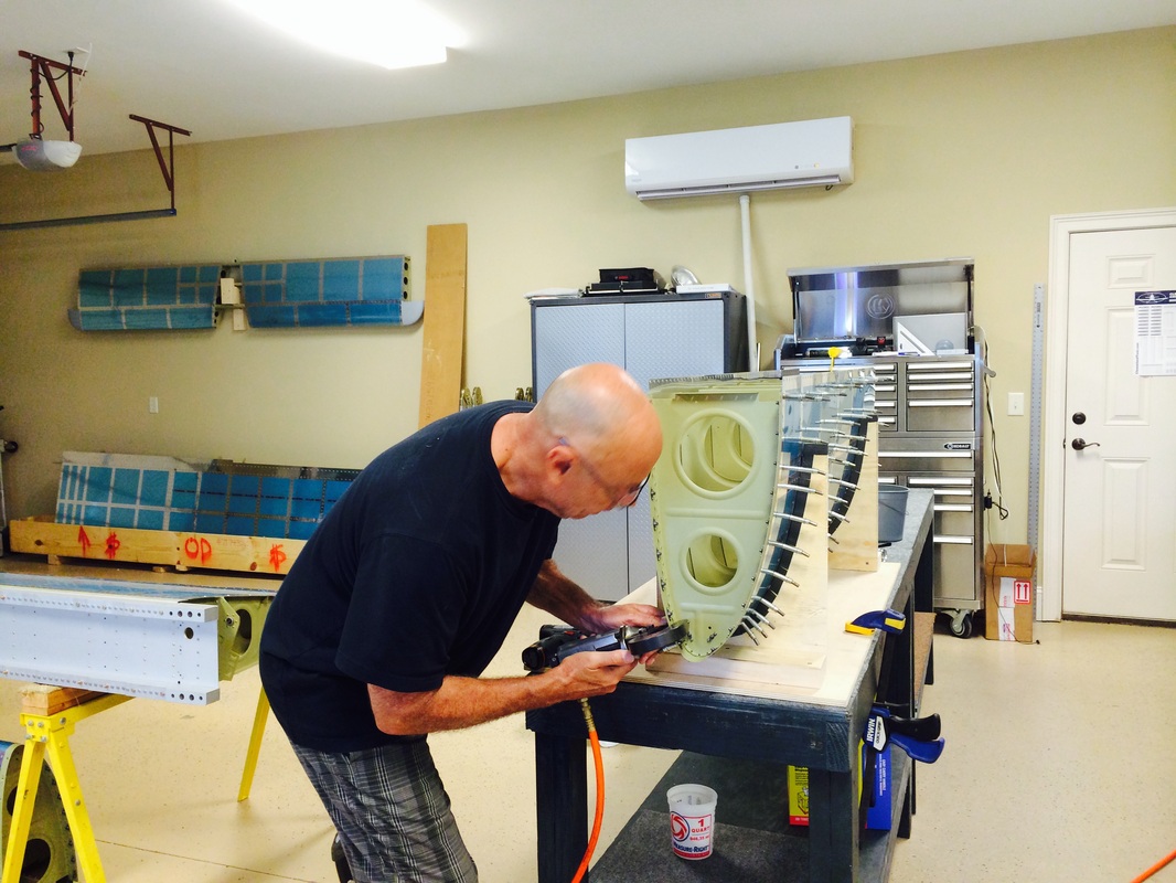
I squeezed all the rivets in the aileron brackets. A few in the middle were just within reach of the deep "C" frame we have, but we made it with a rivet gun in this case.
Ribs attached to the main spar, still to be riveted. Note the spar flanges are also primed with AKZO because of all the counter sinking. This is called out in the plans.
Riveting the parts of the rear spar. Most of this was done with our trusty pneumatic squeezer. It is a great tool once you have learned how to properly use it.
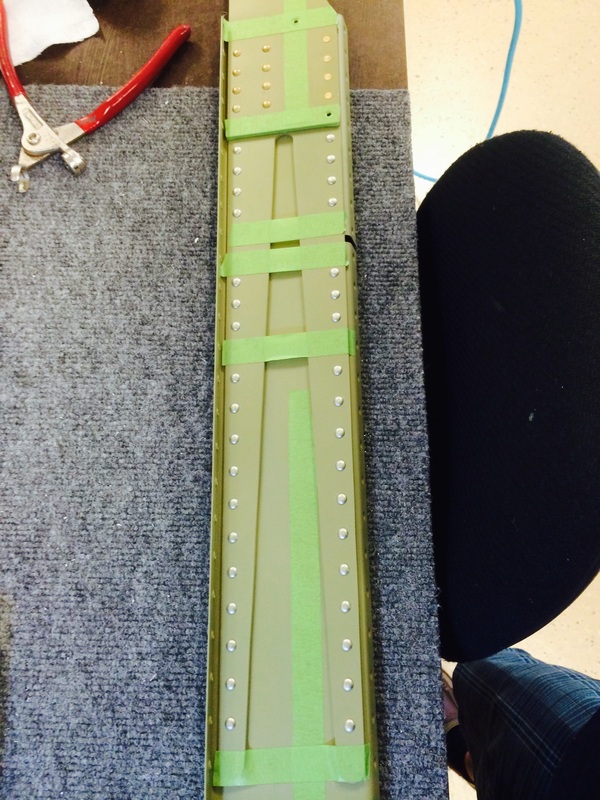
Tape covers up the holes the won't be riveted yet.
Attaching the ribs to the front and rear spar.
Top skin in place, let the skin riveting begin.
Dimpling the top skin in the Avery dimpling frame. This produces the best dimples by far. Using a hand dimpler is ok for small parts, but does not work well on larger parts, especially skin edges.
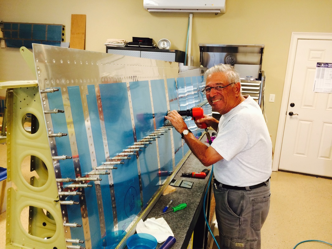
Rafa doing the driving with me on the tungsten bucking bar.
You can see the really good results of out oversize mushroom head, it works better then any other method we have tried including back riveting with a 12" back rivet set, which does not form the best shop heads
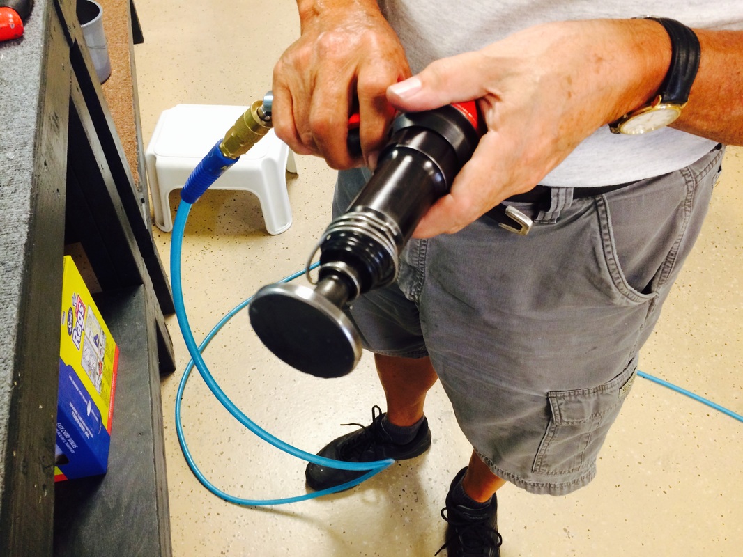
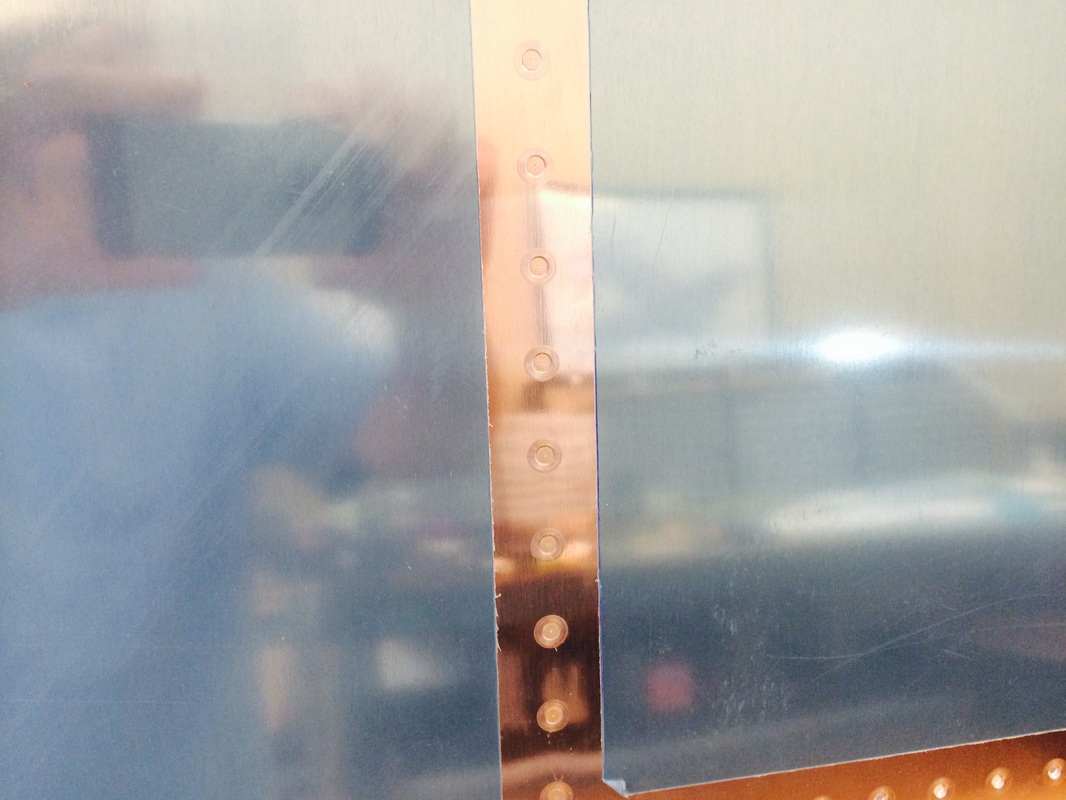
This is a beast, over 2" in diameter, and it does a really good job without any skin deformation. We cover it with clear plastic packing tape to limit surface marks.

More riveting, check out how smooth the skin is after riveting.
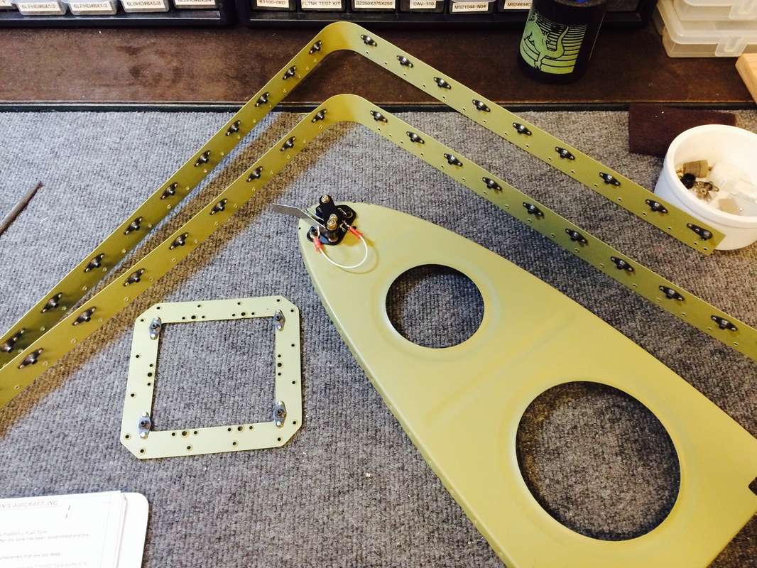
Assembling the tank to skin mounting strip with many plate nuts.
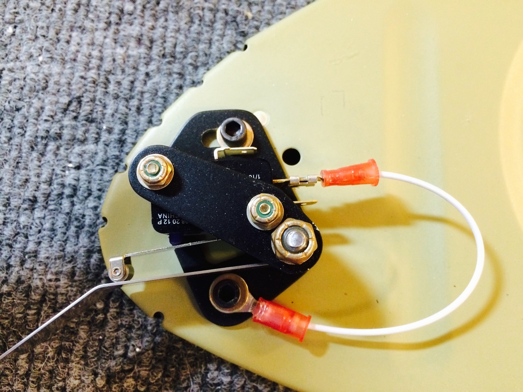
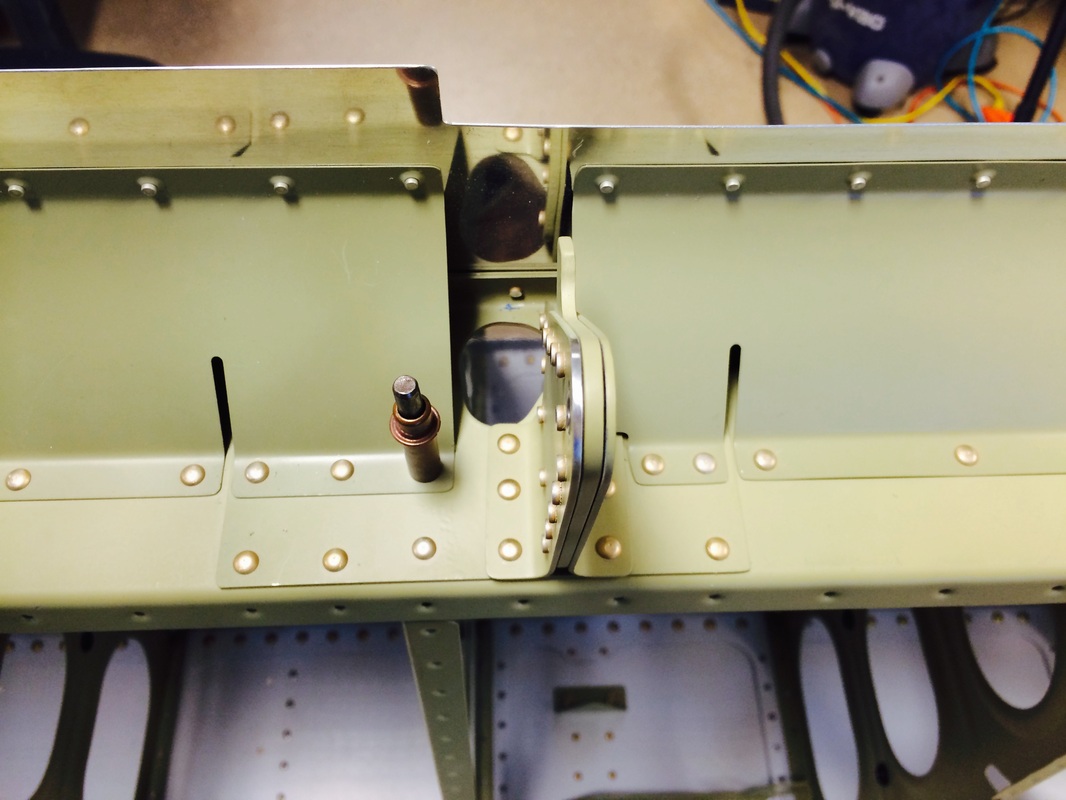
The stall warning tab and switch unit mounted to the rib.
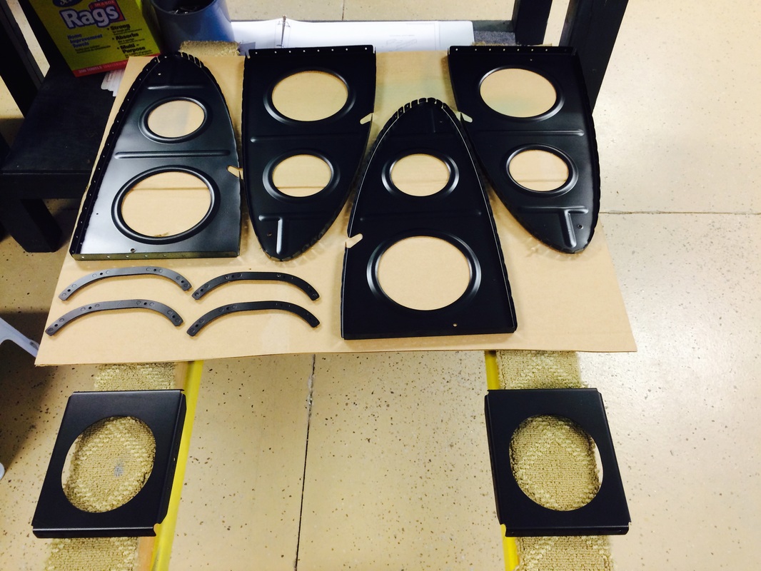
These ribs are in the landing light rib bay and needed to be painted. We chose satin black, we thought it would look best with the shinny LED lights.
Rafael isn't actually drilling a hole through the skin with a Bosch Li-Ion drill, he is drilling out a slightly fubar rivet. We are experts at this procedure, although we rarely ever have to do it!
Squeeze riveting the tank attach bracket and the rib to the outboard skin and rib.
Holy shit! I think I just riveted my finger to the ribs, now what?

Looks nice with the AKZO primed ribs and the satin black lighting bay, and the Alcad skins. This works for us.
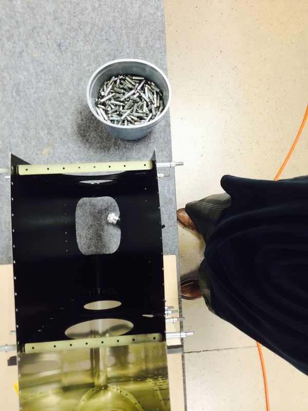
A shot looking through the landing light hole. It is dark in the rib bay!
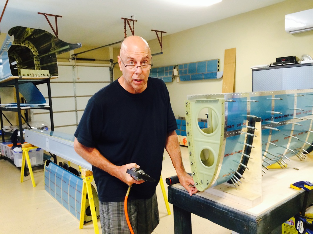
At this stage, we have already riveted the ribs of the leading edge outboard section to the spar and we are now riveting the wing skin to the main wing spar.
Rafael manning the 3X gun with the 2" mushroom head. The skin is matching up nicely because we used the Cleveland Tool edge forming tool before we dimpled the skin.
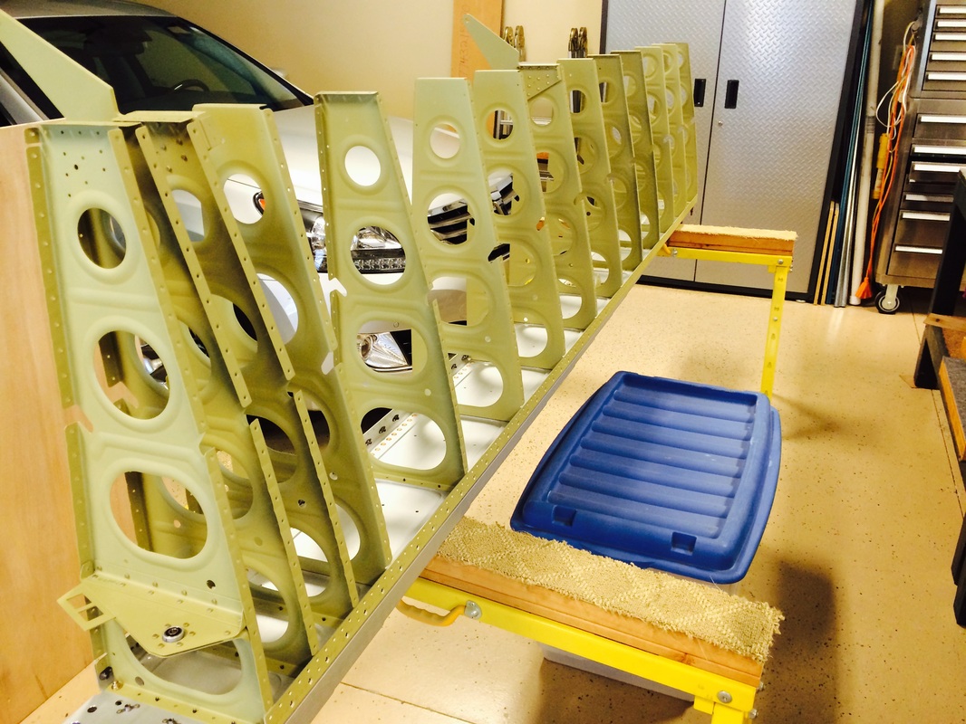
I made the wing caddy last week and patterned it after the one I built for the RV 7A since it worked so well. I put it on locking castors so we can move it around. We used it to rivet the outboard leading edge sections to the main spar. It offers really great access from both sides, but you have to take out the wing you're not riveting.
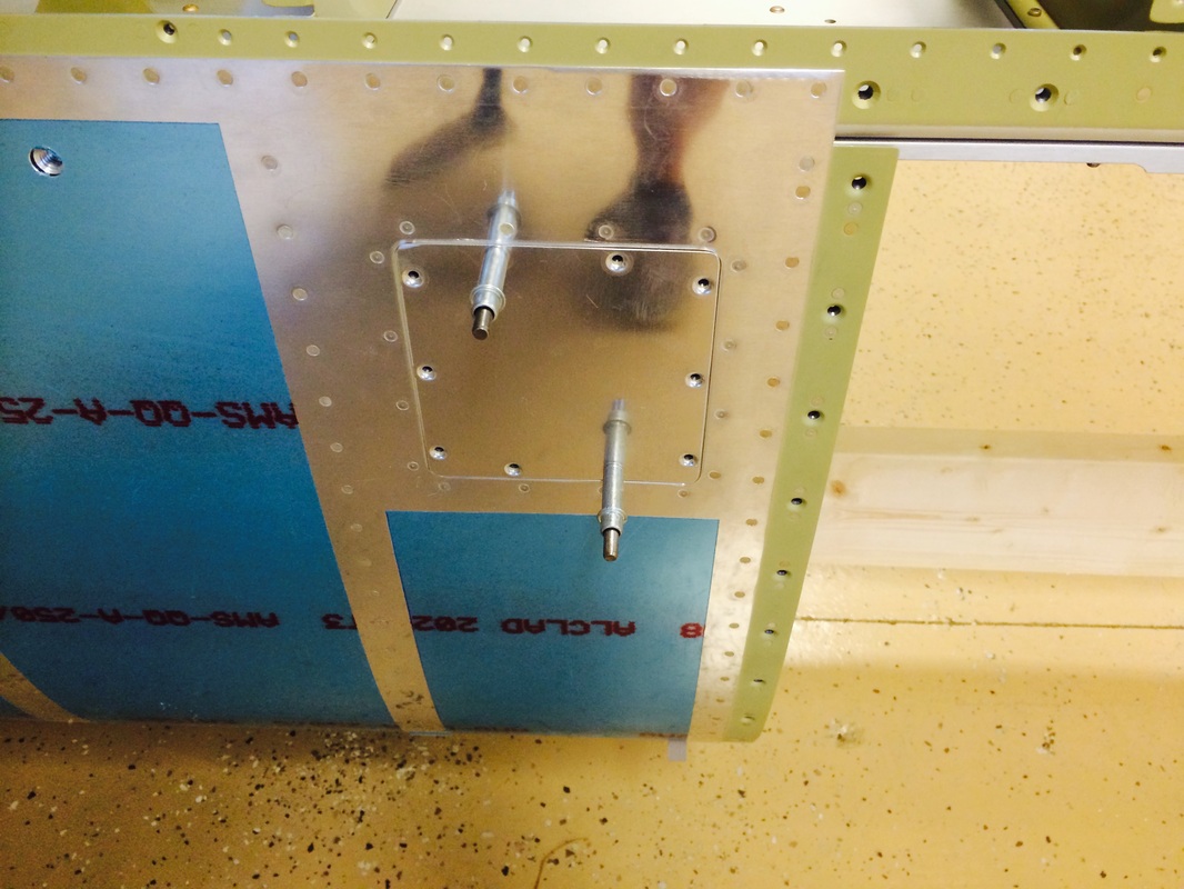
This is the access hatch for the stall warning sensor.
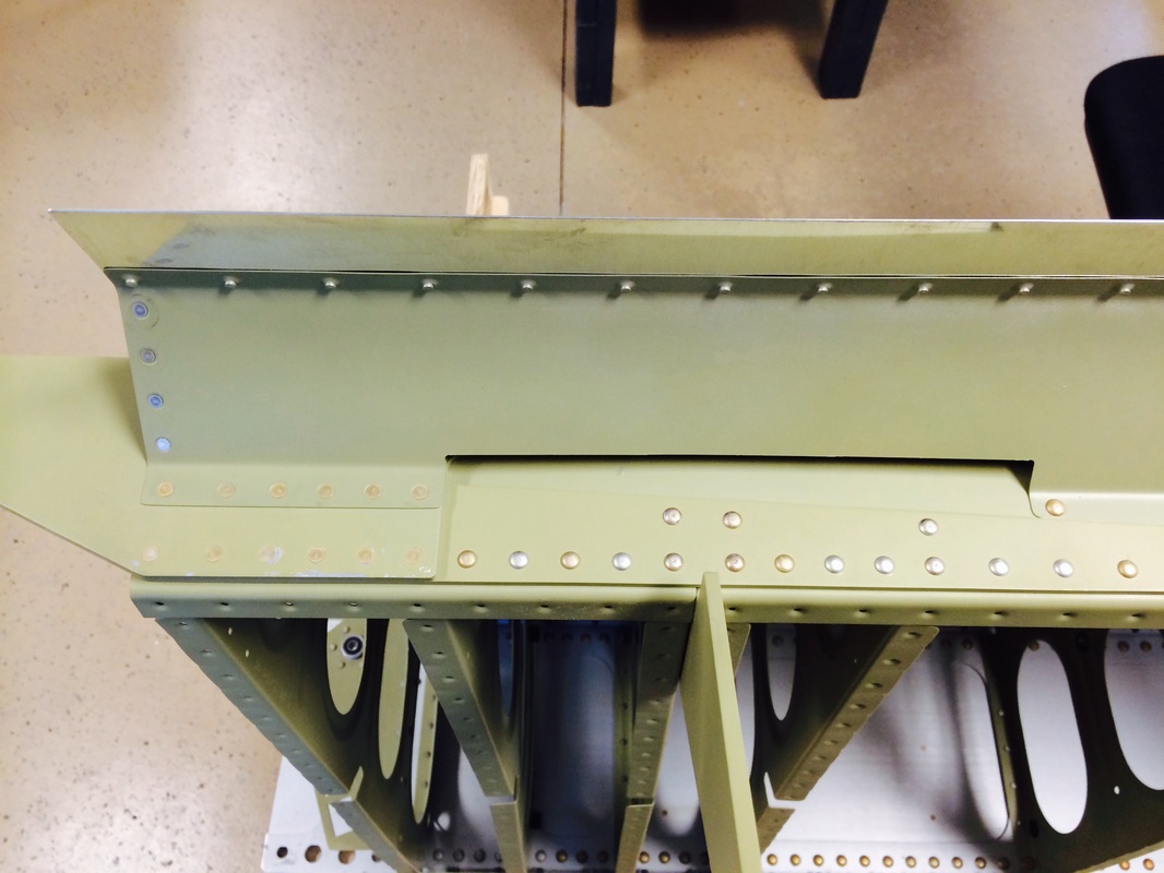
Today we added the skin to rear spar fairing. See the next two pictures for more views.

All of these rivets were squeezed except the one with the cleco in it. I just could not get the C frame in position, so we'll rivet it the old fashion way.
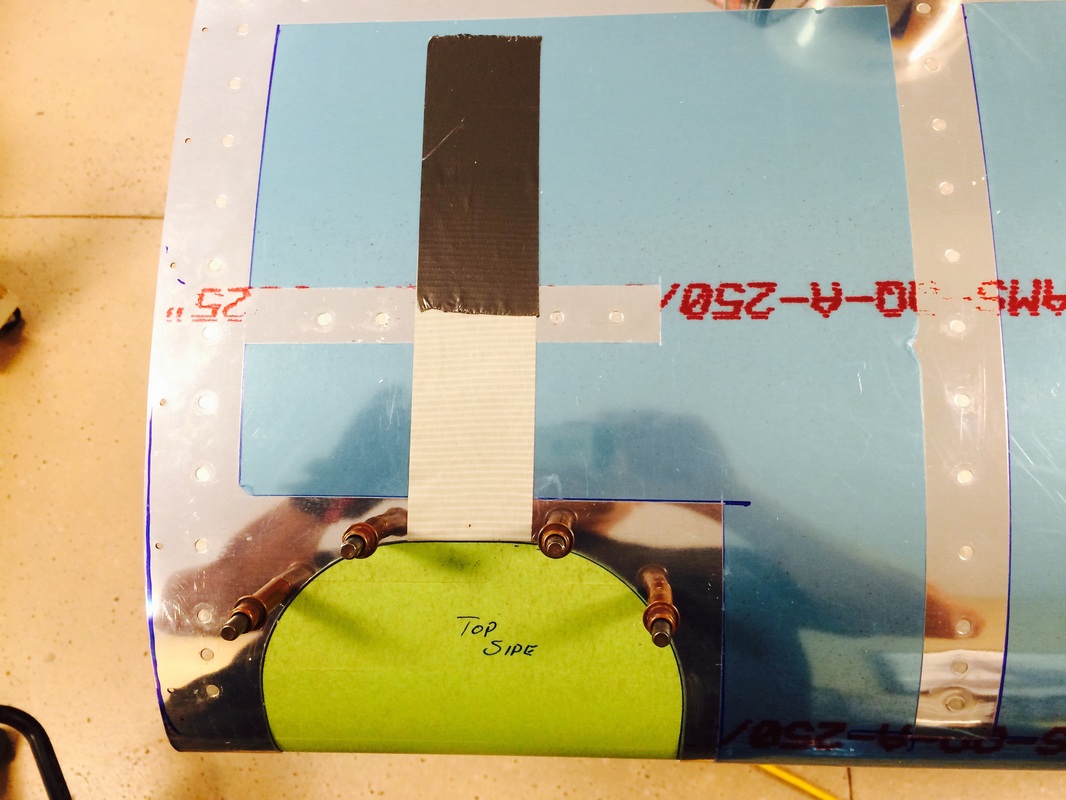
This is where the plans show tape to hold it tight to the skin by pulling out . We double backed the duct tape to pull the tight against the skin and reversed the tape to stick to the wing. Then reach in the lightening hole and push the lens while match drilling the 4 screw holes on the top and bottom. It still will not be tight all around the cutout because the shape of the airfoil does not exactly match the lens shape. Close, but not perfect.
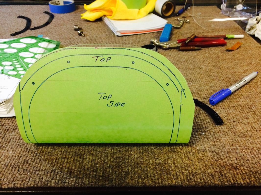
Marking the trim line per the plans before cutting with the Dremel with a cut off wheel.

These are the plate nut brackets, they are held to the lens with black servo tape from my RC helicopters.

The light lens turned out pretty good, I'll add some construction photos when I build the right wing lens.
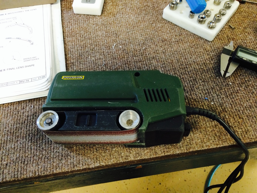
This is one of my favorite tools. Made by Proxxon, it is a very good quality belt sander the get used constantly on the RV. I finished off the plexi edges with this and 240 grit belts. I will also hit the edges with a buffing wheel and some rough to take off the sanding marks. Yes this is more than required, but it only take a few minutes.
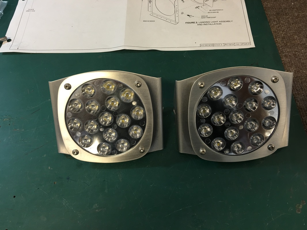
The lights are a new addition to the wings. The Aero Led kit just was released after the avionics cable, about a year after we built the wing. We were not ready for them until now, so the timing was good
The one page plans call for 5/16" spaces, but they really need to be 3/8" which is the thickness of the Aeroled bezel. It may be a good dimension for the Whalen, or traditional par 36 halogen, but not for these.

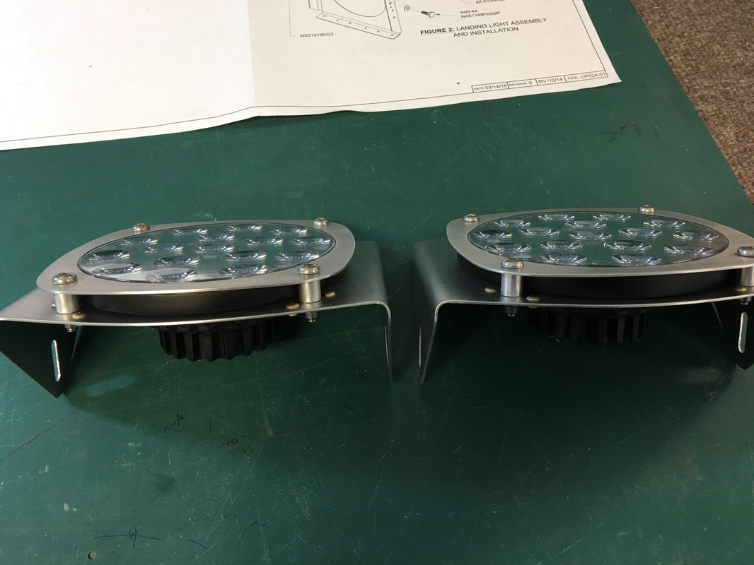
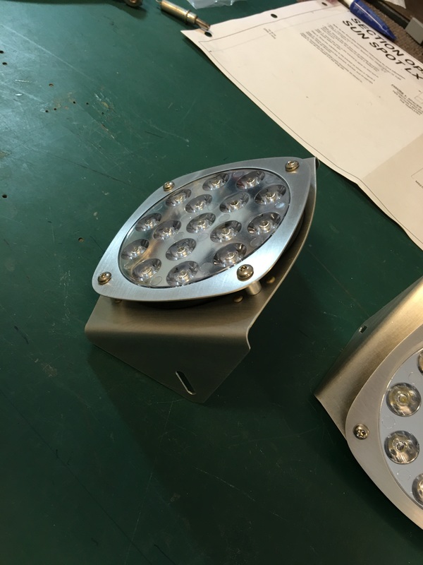
Here is a view of how well it all fits with the 3/8" spaces
