Carl & Rafael's RV 14A Builders Site
  • Home
  • Aiken Airport KAIK
  • Previous Builds
  • Carl's RV 7A
  • Rafael's RV 12
  • About the RV 14
    • RV 14A Specifications
    • RV 14A Performance
  • Work Shop
  • Empennage
    • Kit Delivery
    • Vertical Stabilizer - Sec. 1 thru 6
    • Rudder - Sec. 7
    • Stabilizer - Sec. 8
    • Elevator - Sec. 9
    • Rear Fuselage - Sec. 10 thru 12
  • Wings
    • Kit Delivery
    • Spars - Sec. 13
    • Main Wing Parts - Sec. 14
    • Ribs - Sec. 14
    • Wing Assembly - Sec. 14 Thru 17
    • Fuel Tanks - Sec. 18
    • Bottom Wing Skins - Sec. 20
    • Flaps - Sec. 21
    • Ailerons - Sec. 22
    • Aileron Control System - Sec. 23
    • Wing Tips - Sec. 24
    • Aileron Trim - Optional
  • Fuselage
    • Kit Delivery
    • Mid Fuse Bulkheads - Sec. 25
    • Mid Fuse Lower Structure - Sec. 26
    • Firewall - Sec. 27
    • Fwd Fuse Lower Structure - Sec. 28
    • Fwd Mid Fuse Side Structure - Sec. 29
    • Aft Fuselage Attach - Sec. 30
    • Fuel System - Sec. 31
    • Baggage Area - Sec. 32
    • Interior Painting - End Sec. 32
    • Rudder and Brake Systems - Sec. 33
    • Flap Actuation System - Sec. 34
    • Upper Fwd Fuselage - Sec. 35
    • Aileron & Elevator Systems - Sec. 36
    • Roll Over Structure - Sec. 37
  • Finishing Kit
    • Finishing Kit Delivery
    • Canopy and Window - Sec. 38
    • Seat-backs - Sec. 39
    • Landing Gear and Engine Mount - Sec. 40A
    • Wing Attachment - Sec. 41
    • Miscellanea - Sec. 42
    • Engine & Propeller Delivery
    • Engine Installation - Sec. 43
    • Spinner & Propeller - Sec. 44
    • Cowling - Sec. 45
    • Tricycle Gear Legs & Fairings - Sec. 46A
  • Firewall Forward
    • Engine Specifications
    • Cowl Baffle - Sec. 47
    • Exhaust System - Sec 48
    • Fuel & Oil Systems - Sec. 49
    • Control Cables - Sec. 50
    • Firewall Forward Misc. - Sec. 51
  • Panel & Instrumentation
    • Panel
    • Wiring & Equipment
    • Sensors
    • Avionics
    • Landing Lights - OP52
  • Move to KAIK & Final Ass'y
    • Empennage Installation
    • Wing Installation
    • Odds and Ends
  • Fiberglass & Body work
  • Weight & Balance
  • FAA Inspection & First Flight
  • Phase I & Changes
  • Interiors
  • Paint Design & Painting
    • Scheme Designers
    • Glo Custom
  • RV Builders Forum
  • RV 14 Builder Sites
  • Builder's Location
  • Closing Thoughts
  • Picture Page

Wing Tips - Section 24

We have decided to make a change from Vans plans on the wing tips installation. Vans uses aircraft hinges for installing the engine cowls and many have adopted this system for installing the wing tips.  Below is an excellent article on how it Mike Bullock did it on his RV 7, we plan on using this on our RV 14.
_export_sites_kitplanes_02_data_media_pdfs_attaching_wingtips.pdf
File Size: 474 kb
File Type: pdf
Download File

Picture
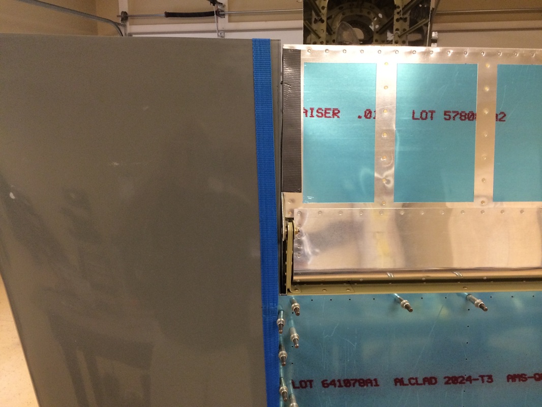
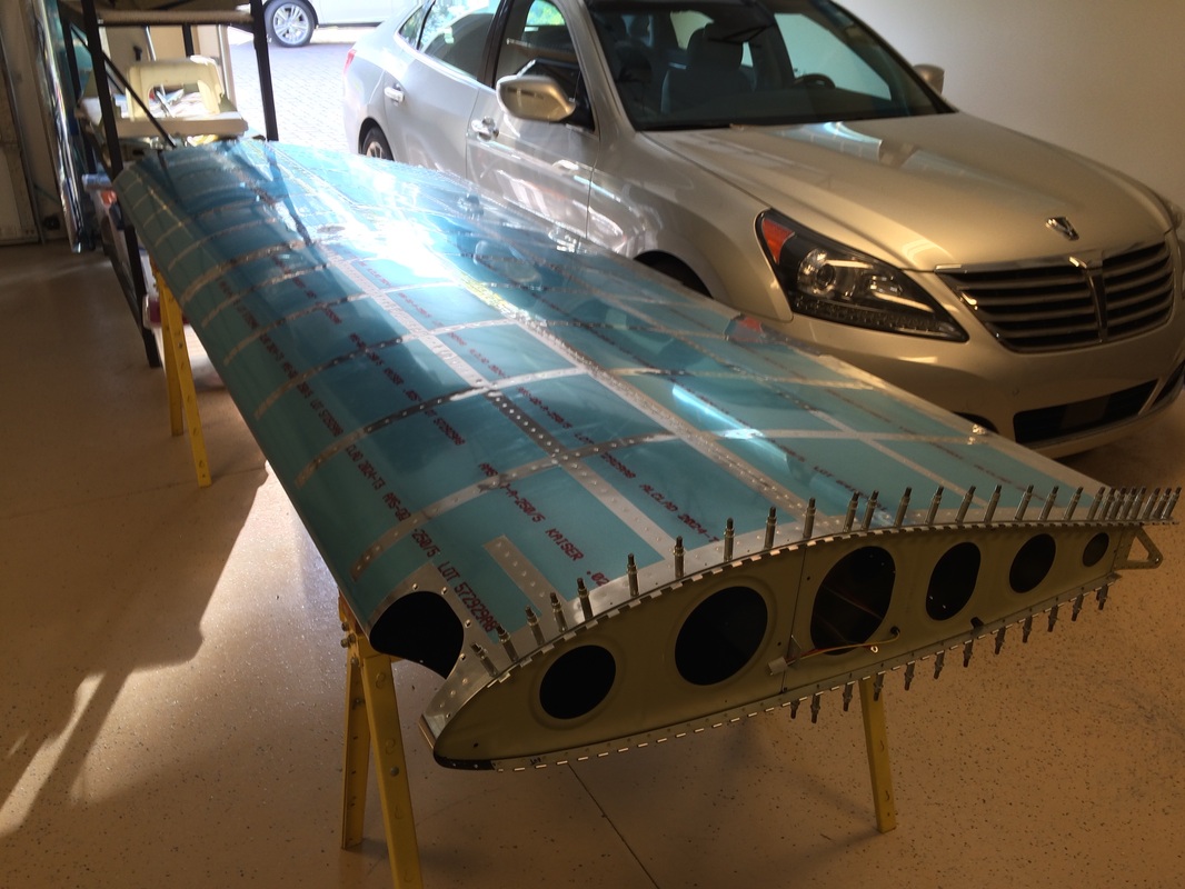
Using the strap to pull the wing tip into position before match drilling the attach hole to the wing skins
Picture
The duck tape is holding the aileron in the proper position based on the alignment tool that is sent in the kit, this is pretty handy and make final alignment much easier. Way to go Van's!
Picture
The rib has to be reversed with the flanges toward the aileron to make the hinge pin attachment method work. This meant modifications to get the hinges in the right place. The hinge on the RV 14 goes in further on the bottom than the other RV's so to compensate I came up with this arrangement.
Picture
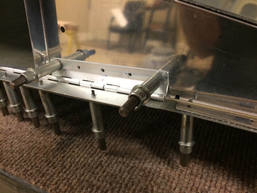
I had to cut off the flange where the hinge extension is and build a new angle flange on the other side of the rib. This allows hinge pin attachment all the way to the aileron. Pretty neat, if I don't say so myself.
Picture
This shows the new flange on the inside of the rib. The rivets are common to the flange, rib and hinge.
Picture
Even though the tip is a little long, Van does this on purpose so the builder can sand them even with the aileron.
Picture
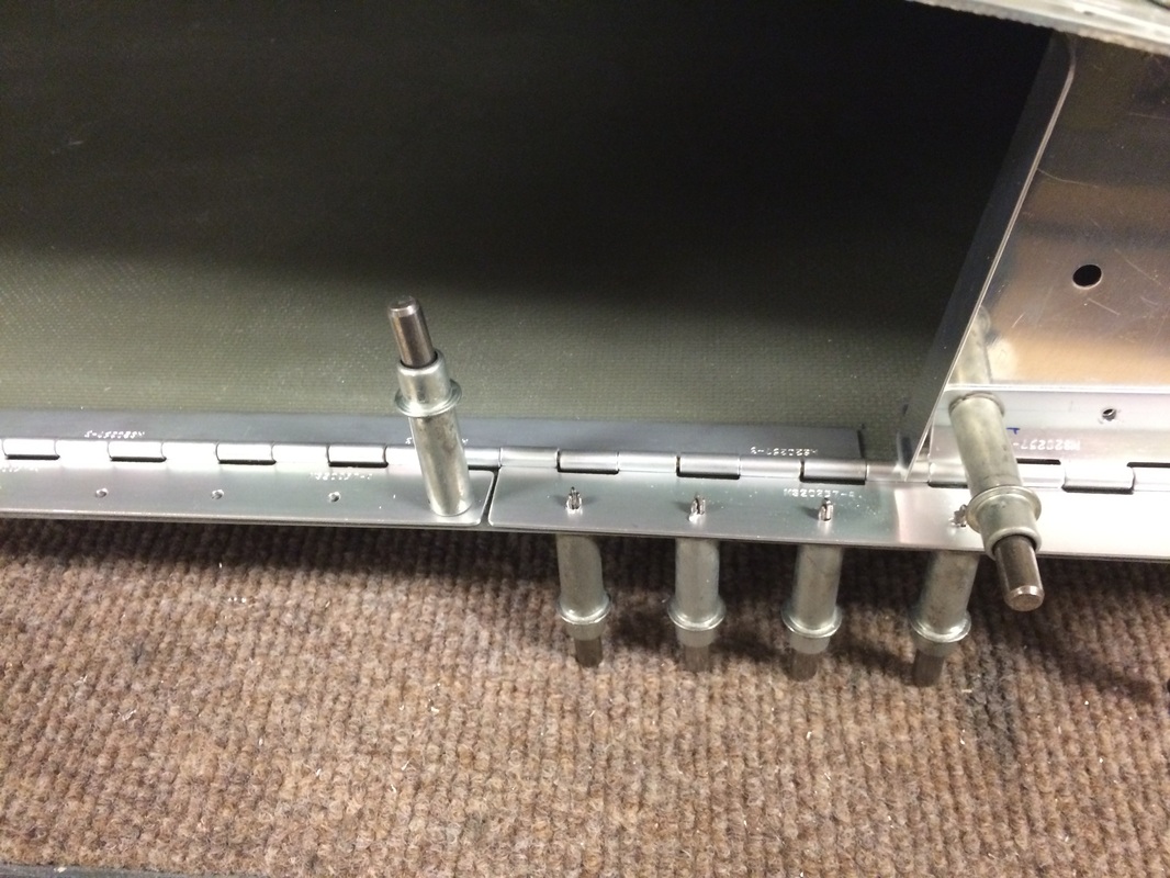
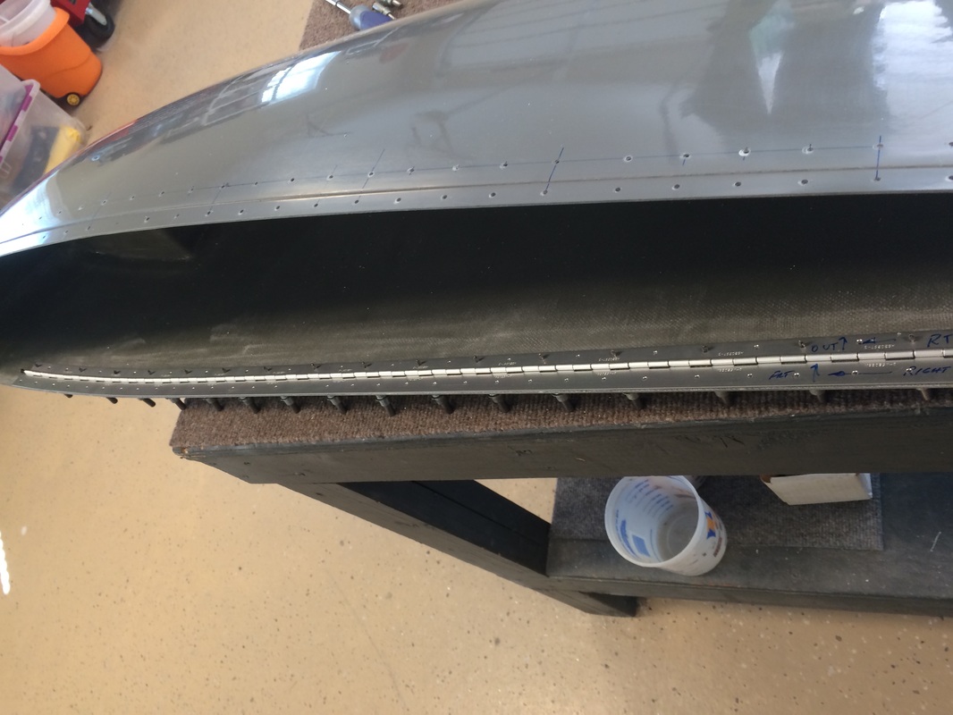
Hinge and rib positioned for riveting
Picture
Drilling for the hinges, this was a lot of work, but I think it will pay off in the long run, and I know it will look better.
Picture
Hinge attachment holes drilled and countersunk.
Picture
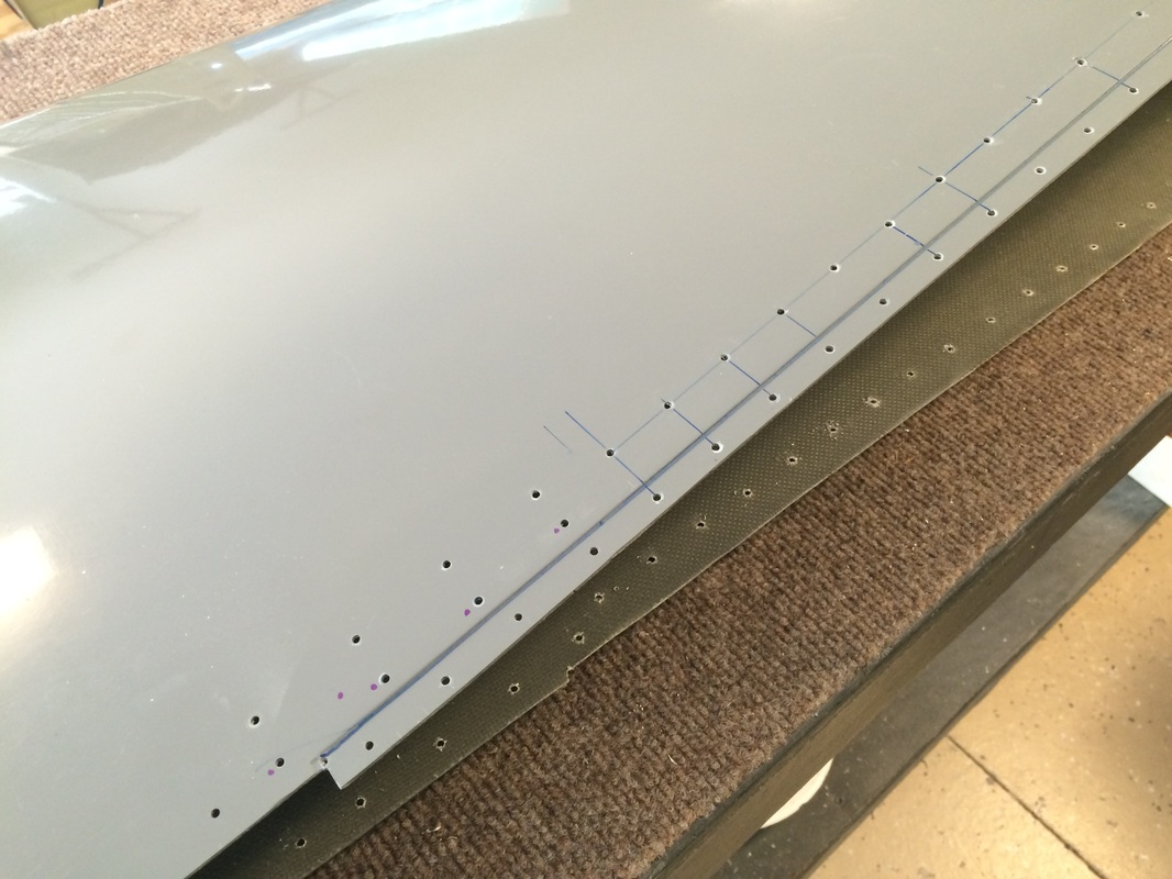
Locating the hinges before we cut the flanges from the wing tip.
Picture
Picture
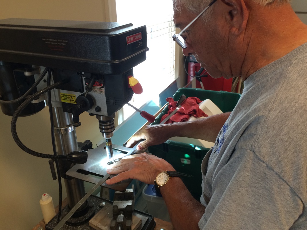
Rafael countersinking the hinge spacing strip cut from the flange of the wing tip.
Picture
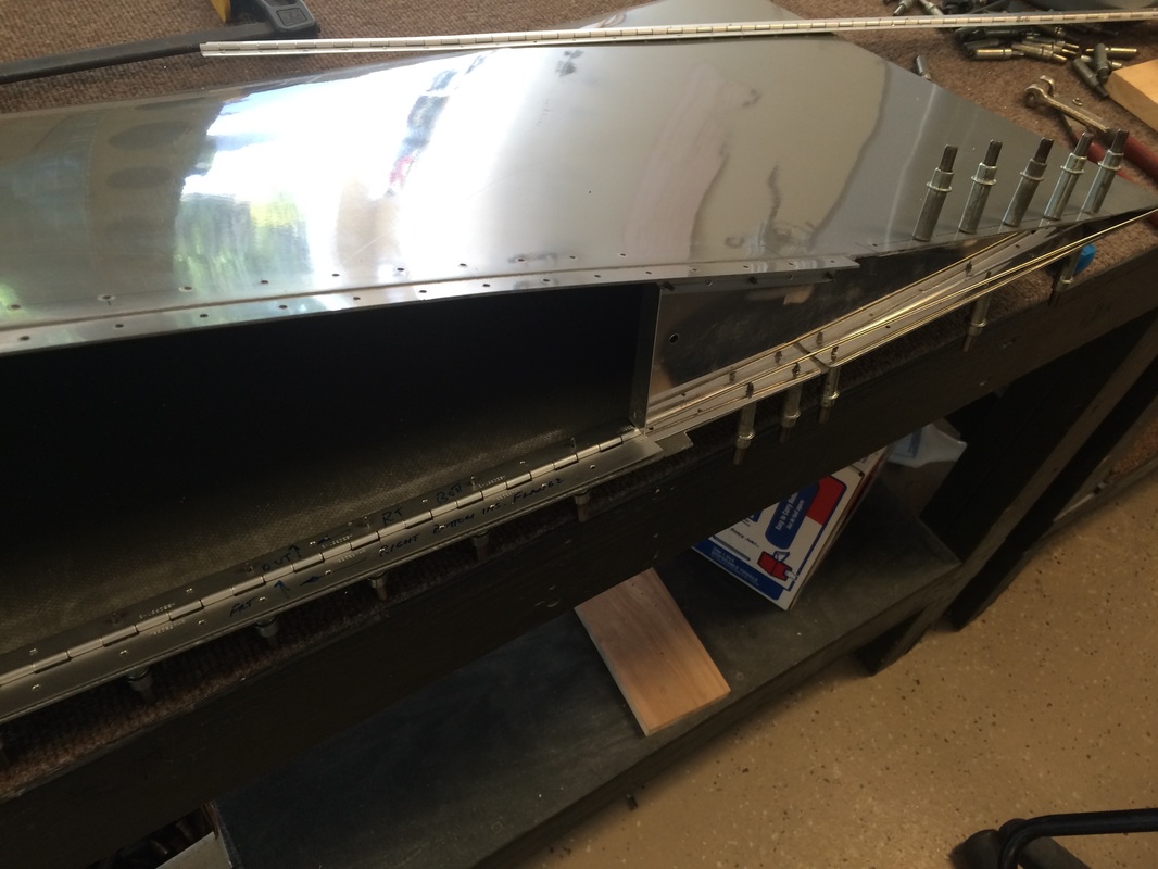
We are riveting the hinges to the wing here with the exception of the bottom rear skin. We have left this skin off until the wiring is complete, too many unanswered question yet.
Picture
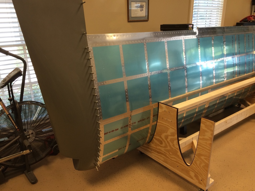
Some final fitting of the tip to the skin joint.
Picture
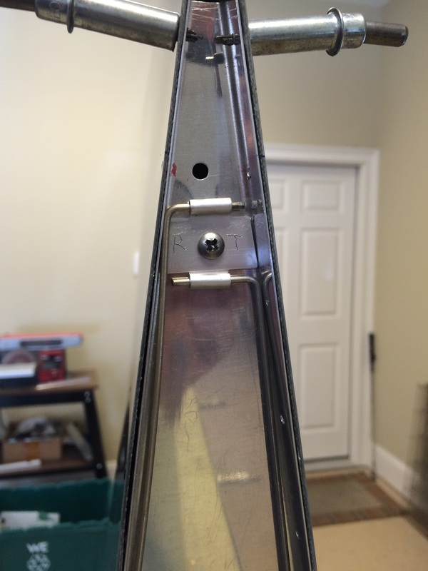
These pieces of hinge is a simple solution to retaining the hinge pin is a very secure way. There is a plate nut on the back side of the rib, remove this #8 screw, pull the pins and the tip is removed.
Picture
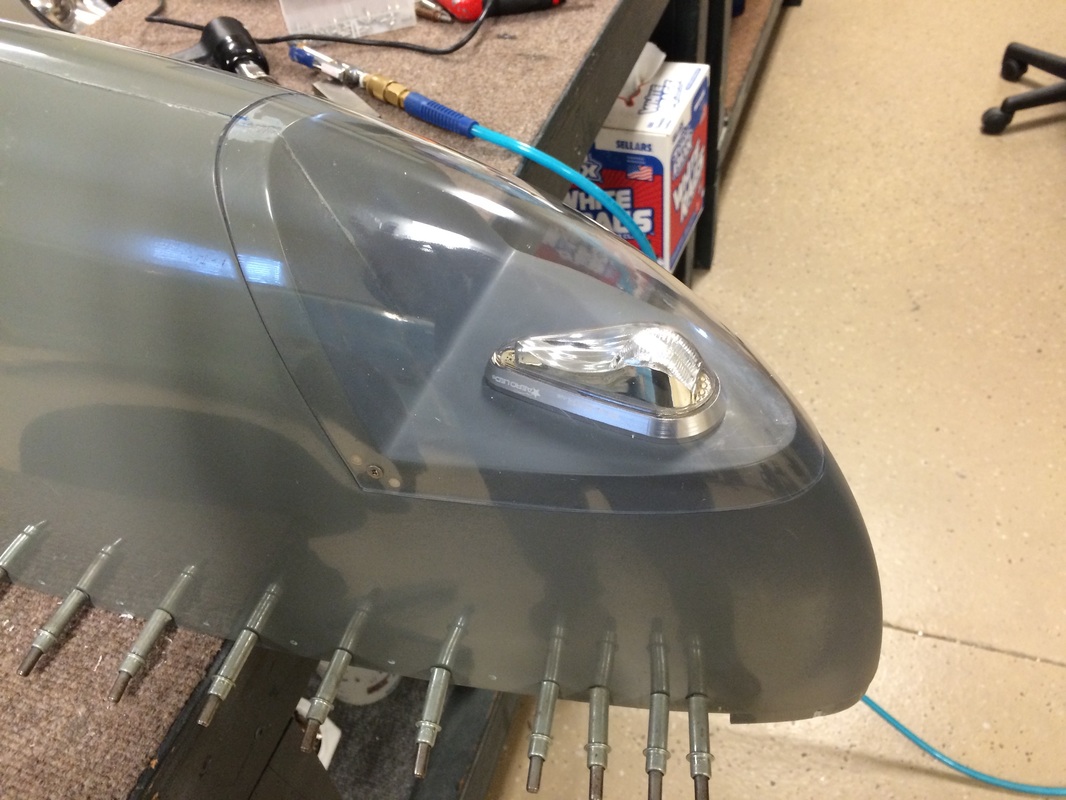
This is the first cut of the position light lens, there where 3 more to get it close and a lot of sanding with the Proxon belt sander to get a good fit.
Picture
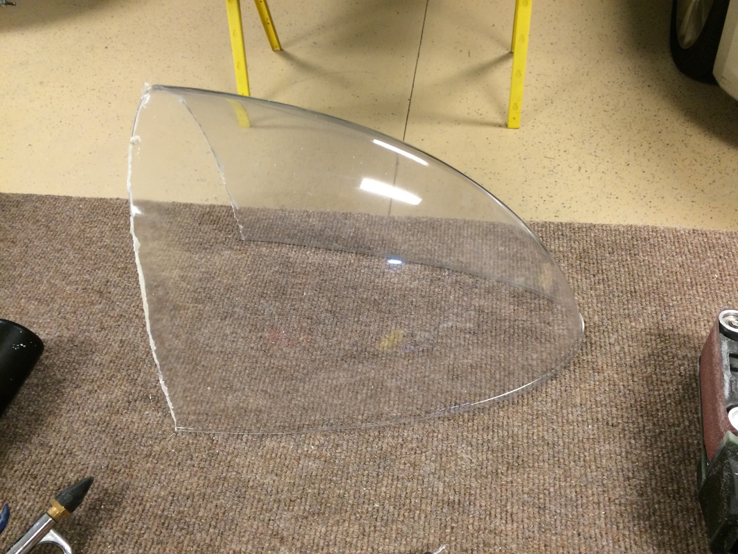
a little fitting and then some sanding and then do it 10 more times to get it close.
Picture
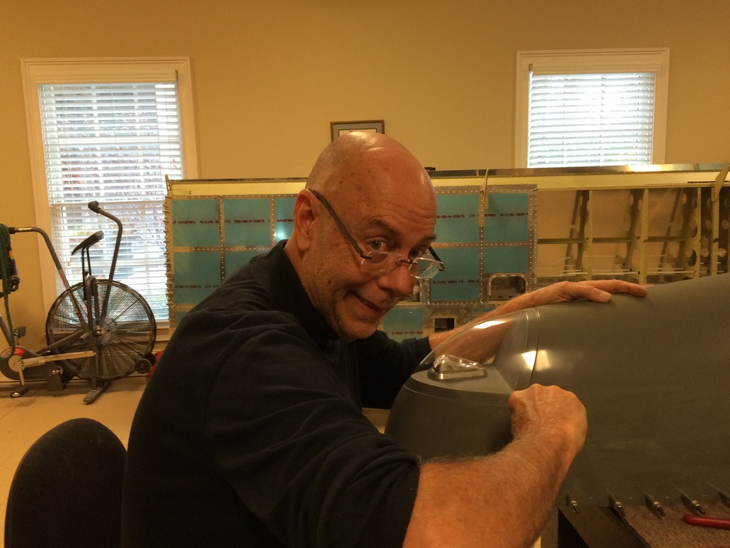
An FAA picture to show who is doing all this building and documenting.
Picture
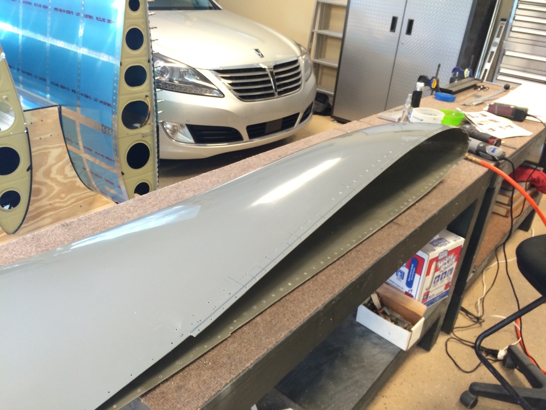
All done except buffing the edges and fixing a few light scratches that happened in shipping.
Powered by Create your own unique website with customizable templates.