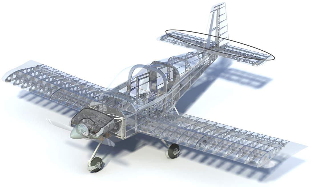
Elevator ribs are two pieces in the RV 14 and there is a secondary spar with bonded high density foam ribs behind the second spar, much different than the RV 7.
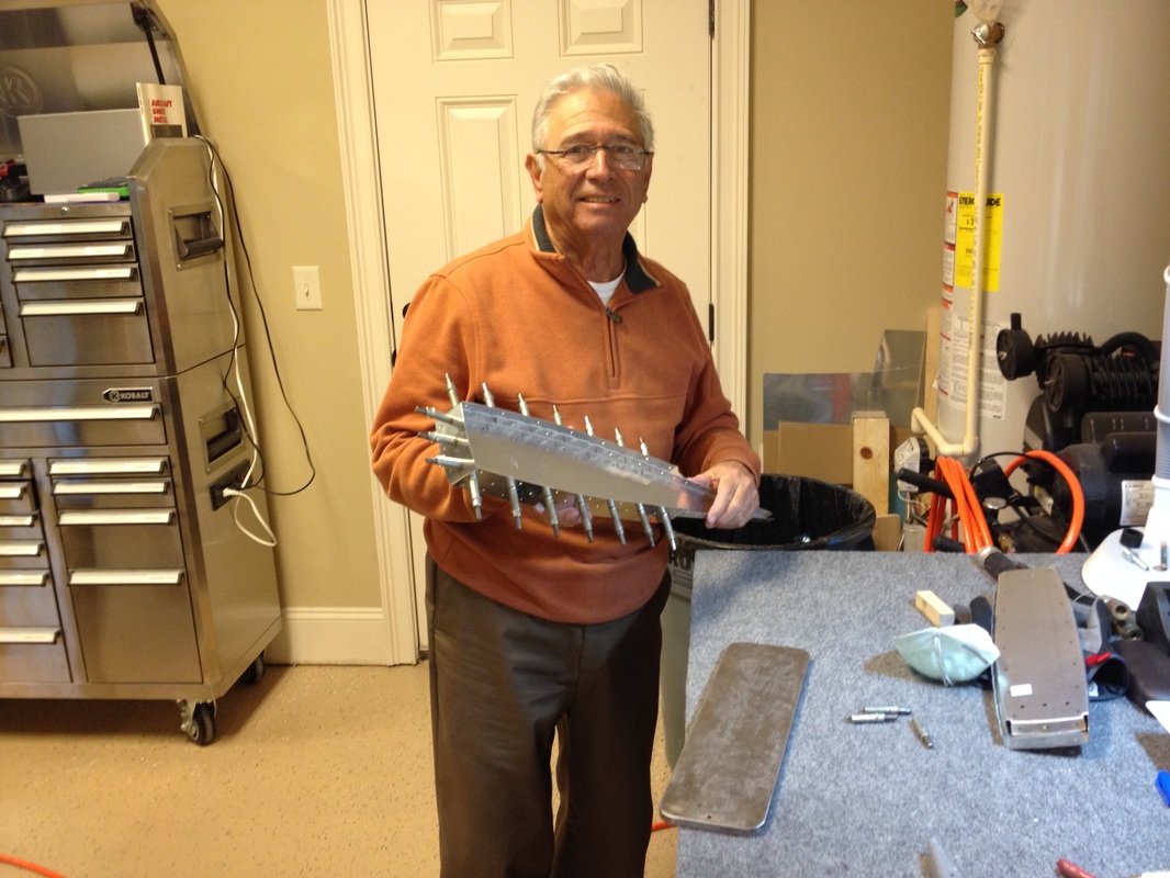
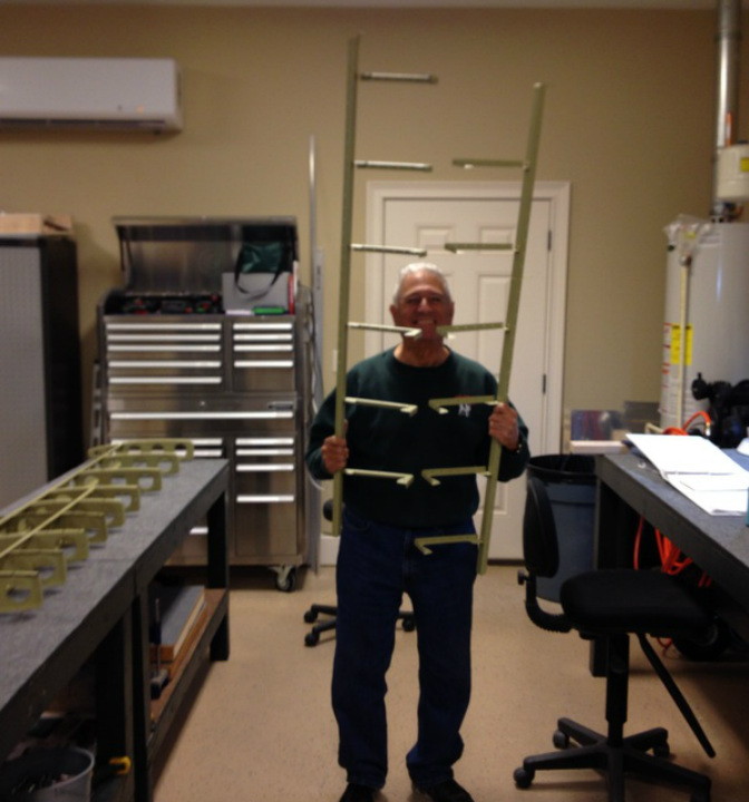
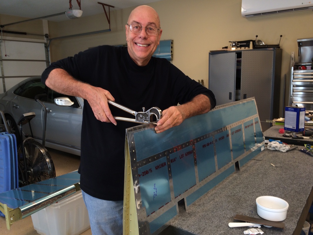
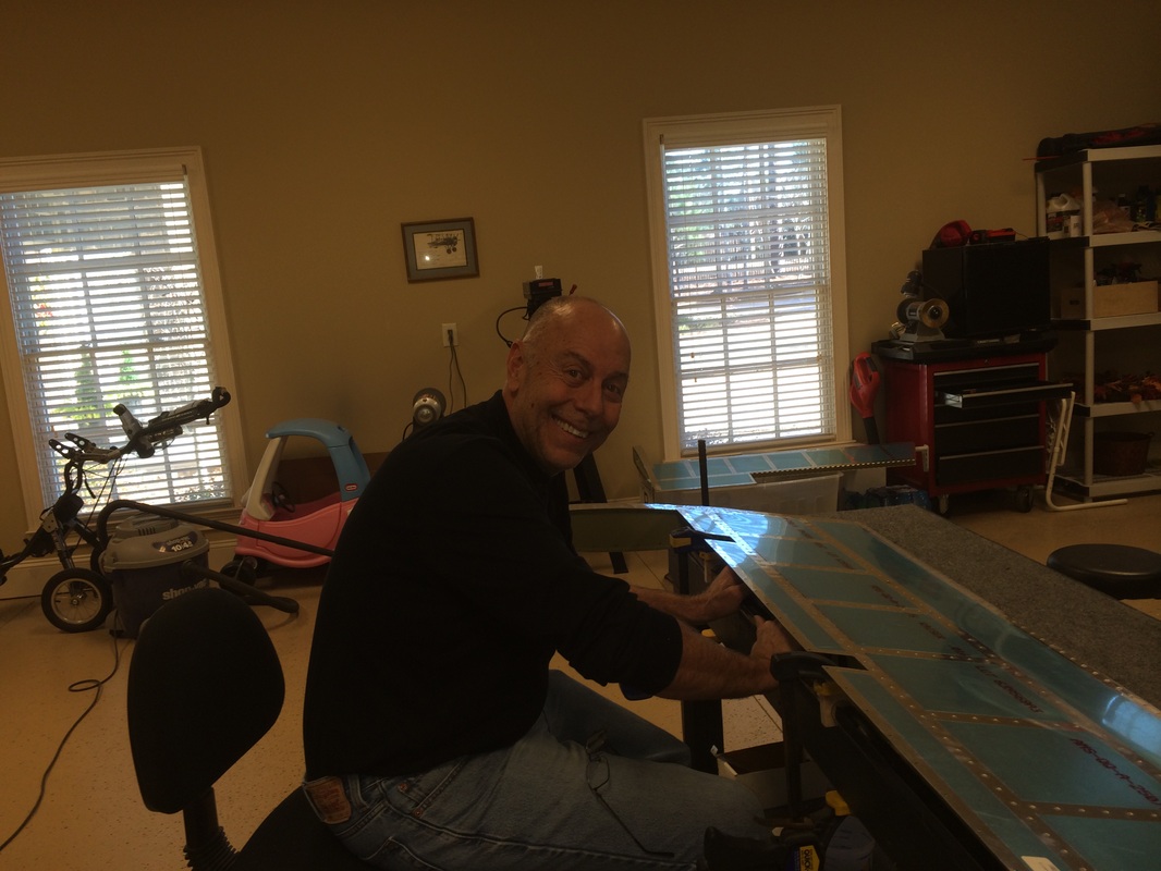
My partner in crime banging out parts, Being an engineer he is deliberate & methodical but has issues ;-) Since I'm doing the web site I get to say what I want!
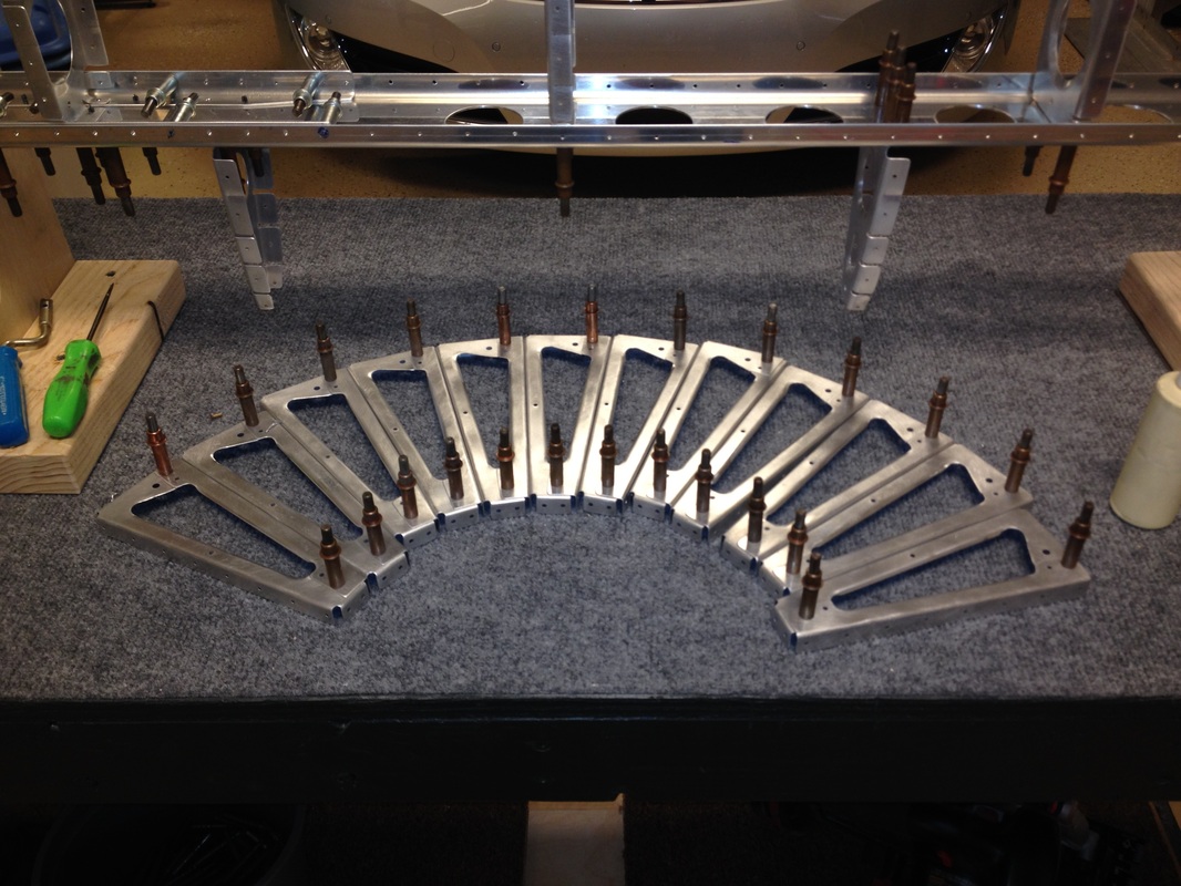
More parts ready for priming
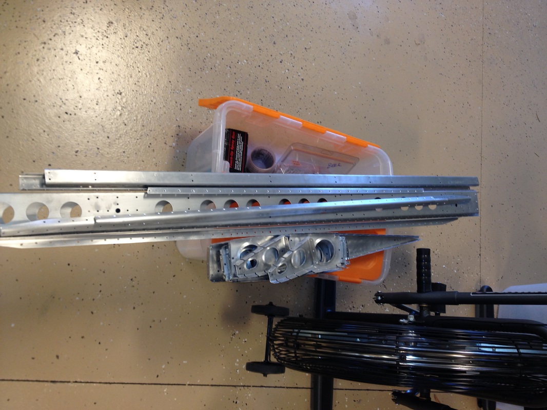
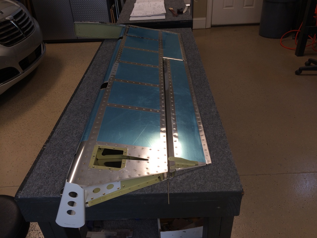
Elevator spas and ribs after priming and assembly
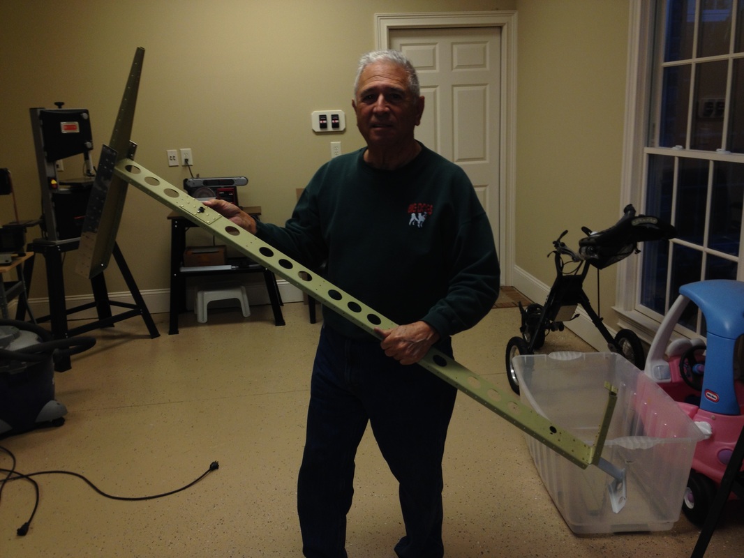
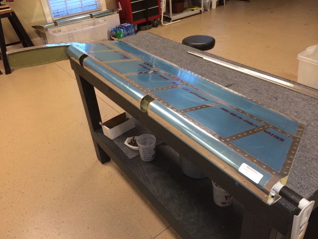
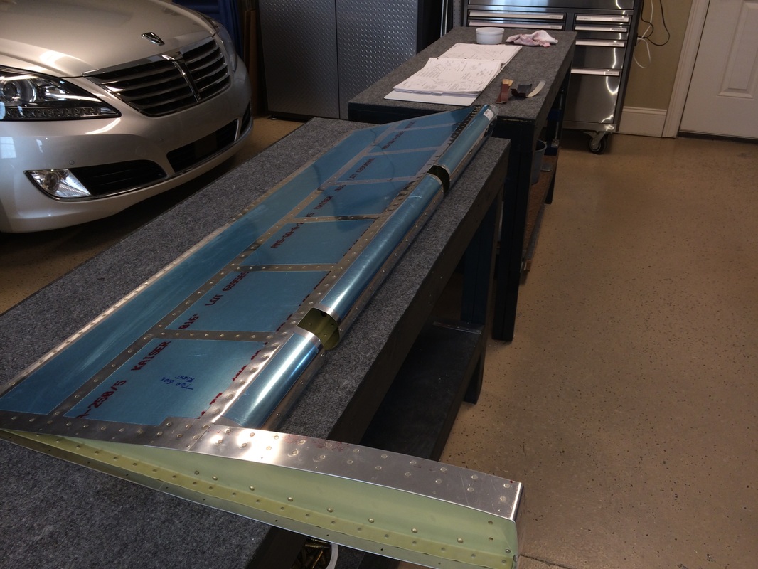
Main elevator spar after priming and assembly. Now ready to put the elevators together.
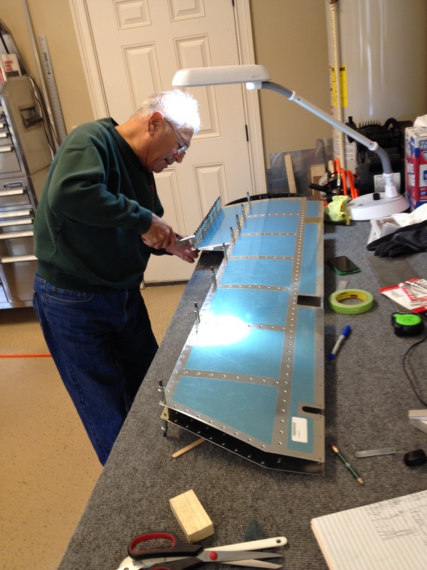
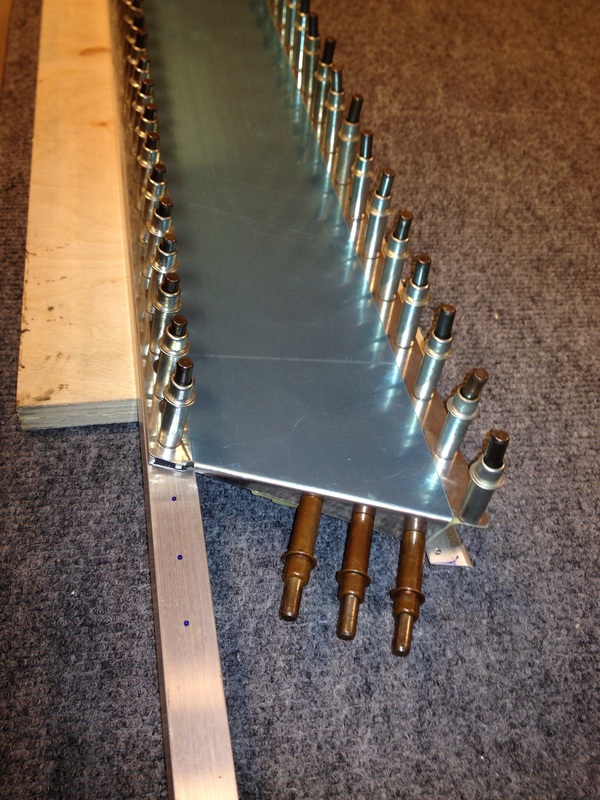
Getting ready to rivet the secondary elevator spar with a very long bucking bar we got from Avery. It works fine by the way, but they are $30.
Trim tab ready for riveting
What a handsome guy! Oh yeah that's me, a legend in my own mind! This is squeezing the elevator rear edge. First half way with regular dies alternating every 5 rivets back and forth and then a final but careful squeeze with the 8 degree tapered die.
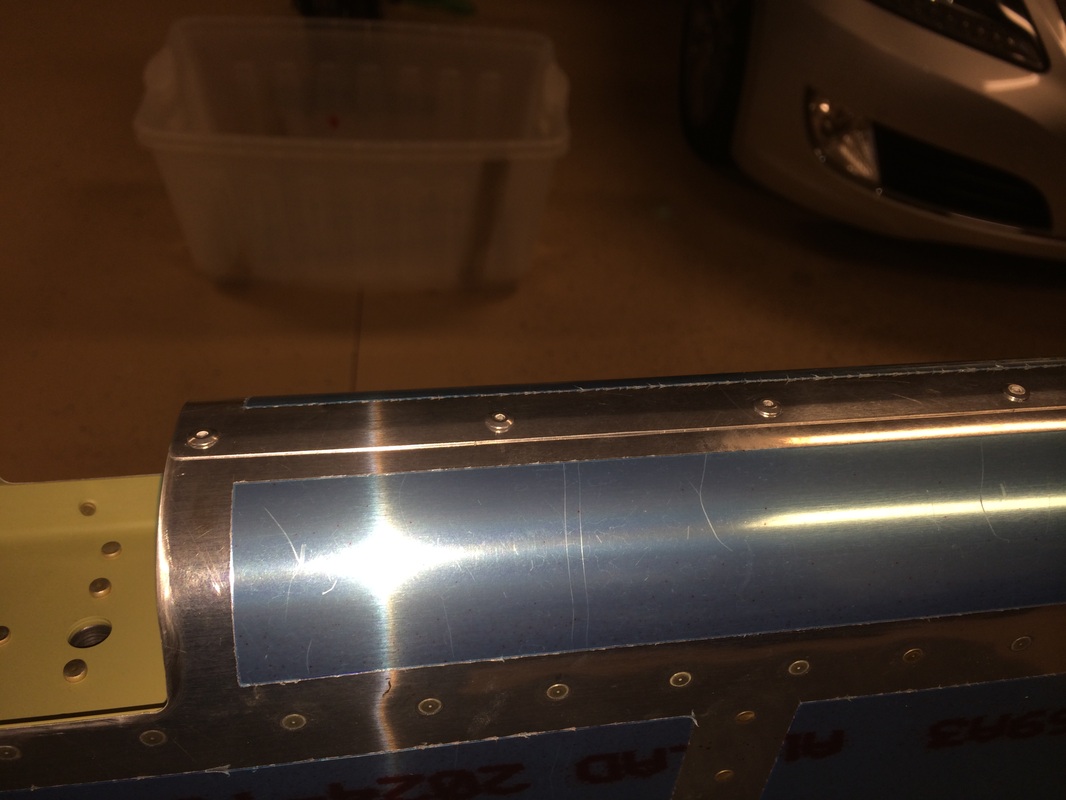
Rolling the elevator leading edges using thick wall PVC pipe of 3/4" and 1"" as required and a set of channel locks to twist while holding down on the table
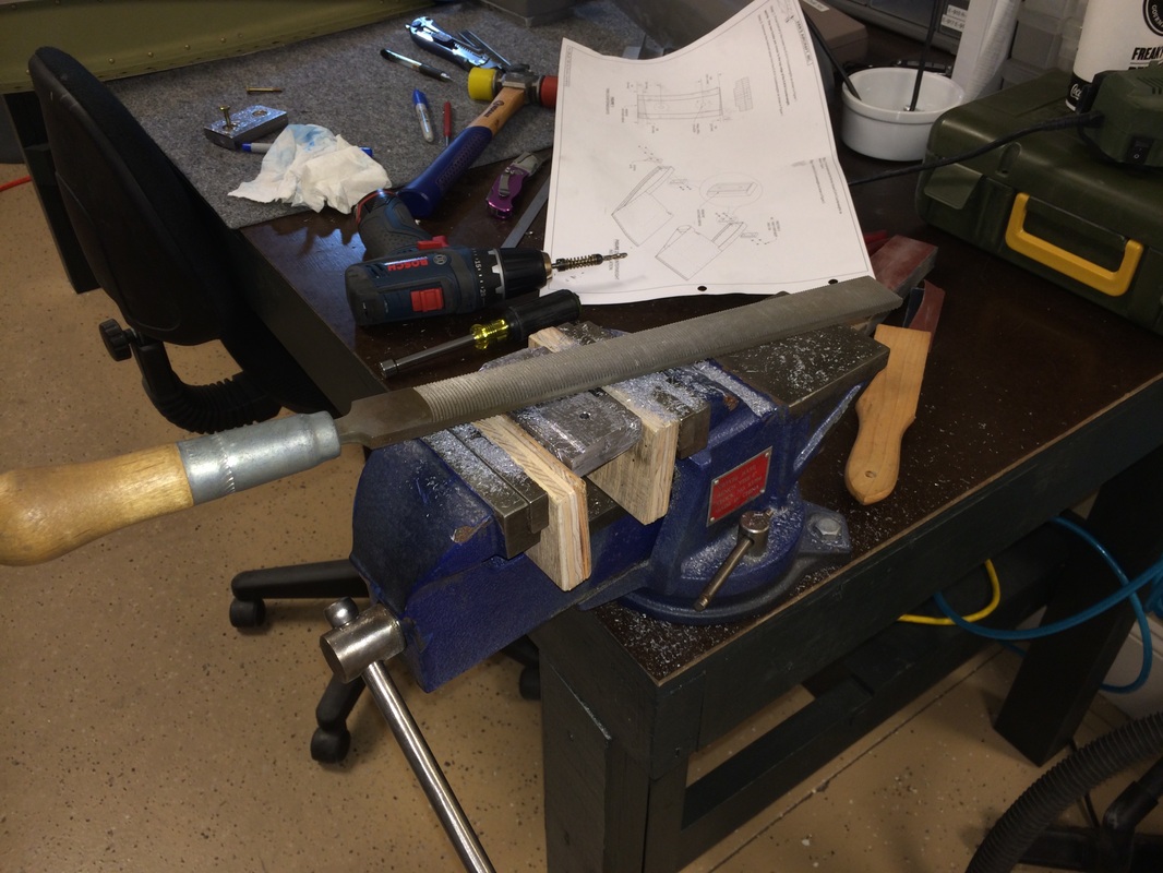
I found it easier to file off the boss on the elevator counter balance weight than to try and cut it for. I used the big tooth vixen file.
Elevator is done except for the fiberglass tip. I use that as filler work when I'm alone
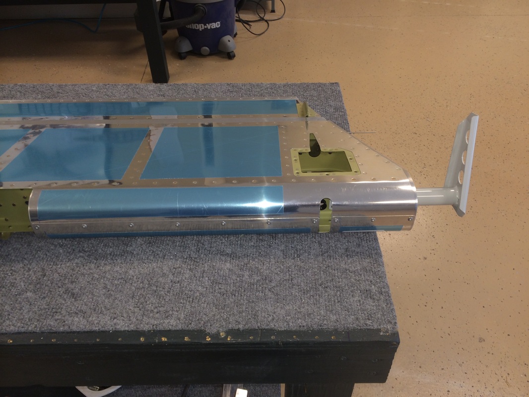

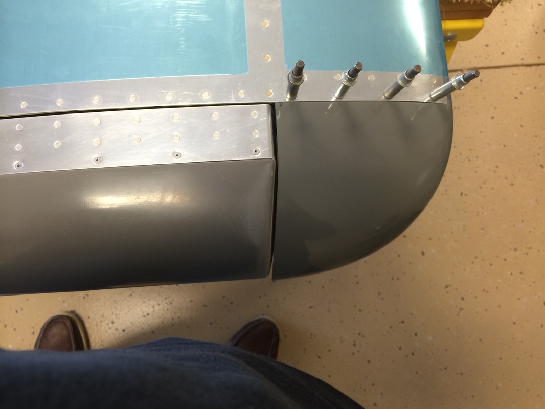
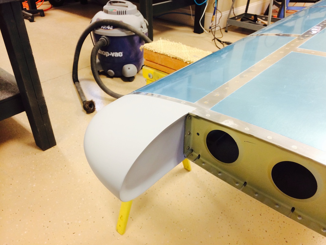
The finished leading edge on the left elevator. You can also see the trim tab motor mounting receptacle
Here I'm starting to Cut back the fiberglass tip to fit properly in the tip rib
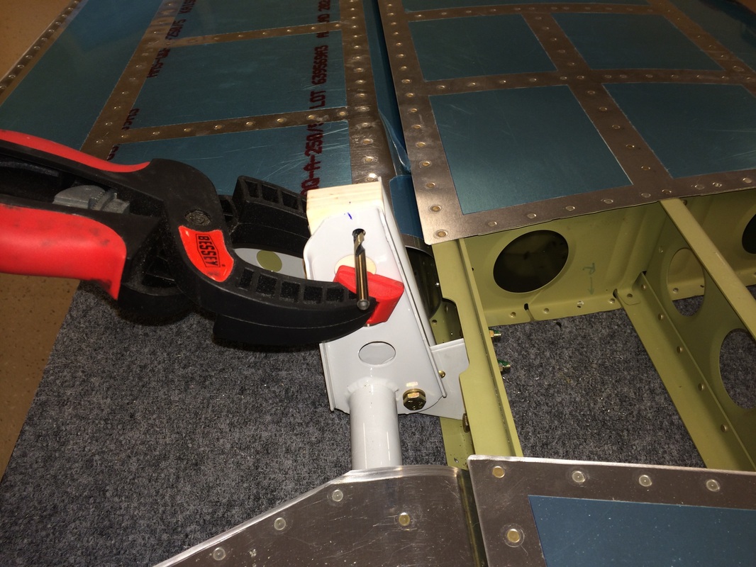
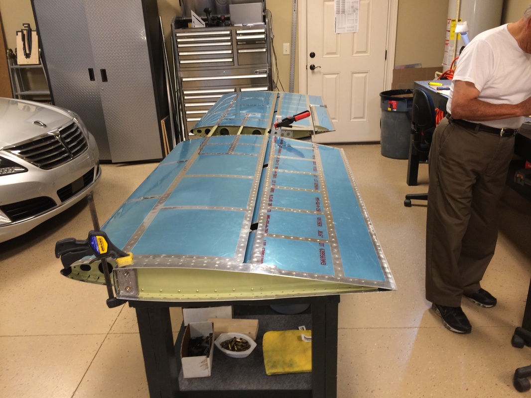
Trouble in Paradise: We were installing the elevators per the manual to drill the horns and noticed a 0.150 inch misalignment in the elevator trailing edge after clamping the balance weight to the stab. We are not sure if the is an issue, but we thought it was best to find out. See note from Rafael and pictures below to Van's
To Van's email support line
We are ready to drill the holes for the elevator push rod. As instructed, we placed the elevators in trail by aligning the forward skins to the horizontal stabilizer. When examining the alignment of the trailing edges, we see a deviation of about 0.17” (as near as I can measure) at the right elevator inboard point.
The procedure we used is as follows:
I first clamped the leading edge counterbalance skins on both elevators to the horizontal stabilizer.
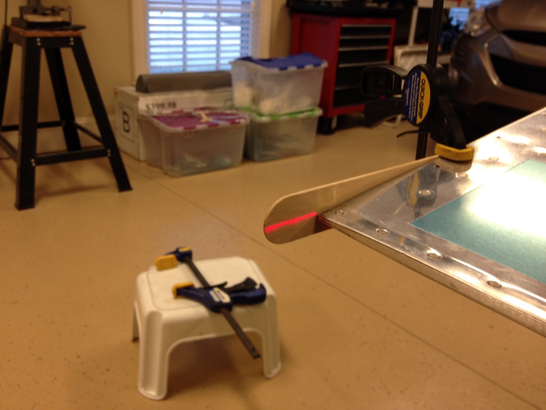
I then set up the laser to be straight between the right and left outboard edge points.
Finally, I took pictures at five points along the trailing edges. As you can see, the maximum deviation occurs at the inboard edge of the right elevator.
1. What do you think the effect of this error will be?
2. Is this going to require extra trim tabs or other corrective action?
3. We are leaning towards aligning the counterbalance skins as opposed to mis-aligning them to minimizing the trailing edge variation. Do you agree?
4. Would you please comment on how typical these results are?
Thanks and best regards,
Rafael
To Van's email support line
We are ready to drill the holes for the elevator push rod. As instructed, we placed the elevators in trail by aligning the forward skins to the horizontal stabilizer. When examining the alignment of the trailing edges, we see a deviation of about 0.17” (as near as I can measure) at the right elevator inboard point.
The procedure we used is as follows:
I first clamped the leading edge counterbalance skins on both elevators to the horizontal stabilizer.
I then set up the laser to be straight between the right and left outboard edge points.
Finally, I took pictures at five points along the trailing edges. As you can see, the maximum deviation occurs at the inboard edge of the right elevator.
1. What do you think the effect of this error will be?
2. Is this going to require extra trim tabs or other corrective action?
3. We are leaning towards aligning the counterbalance skins as opposed to mis-aligning them to minimizing the trailing edge variation. Do you agree?
4. Would you please comment on how typical these results are?
Thanks and best regards,
Rafael

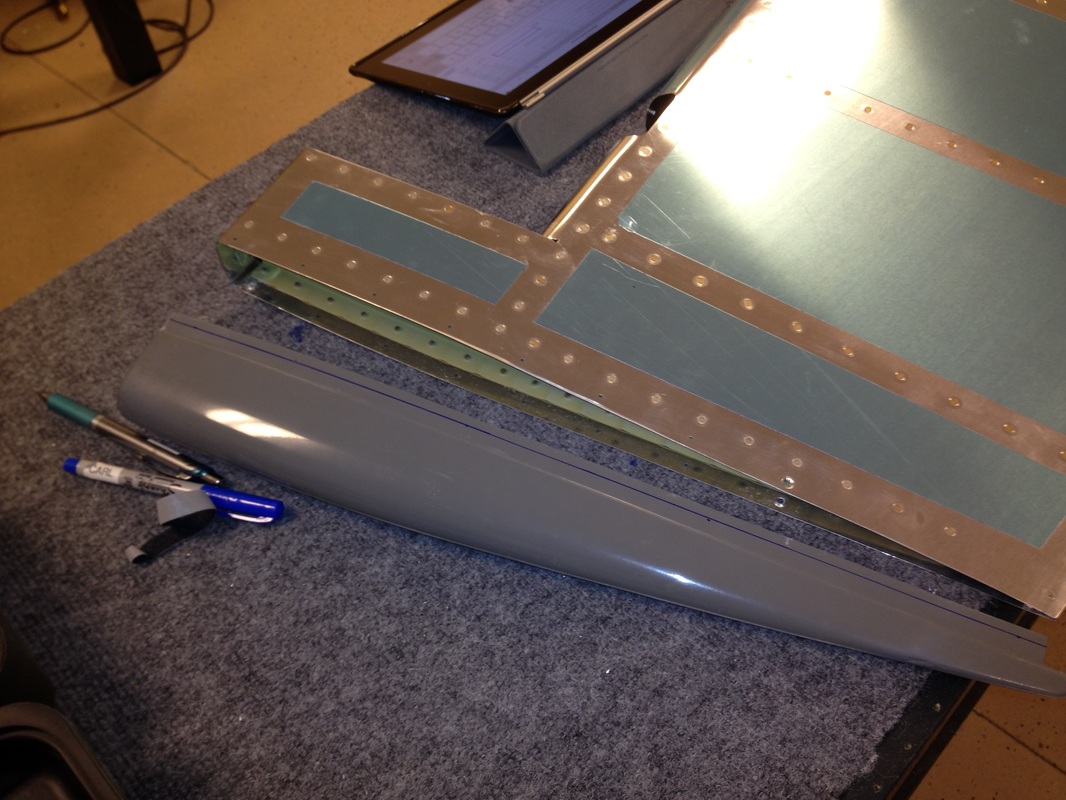
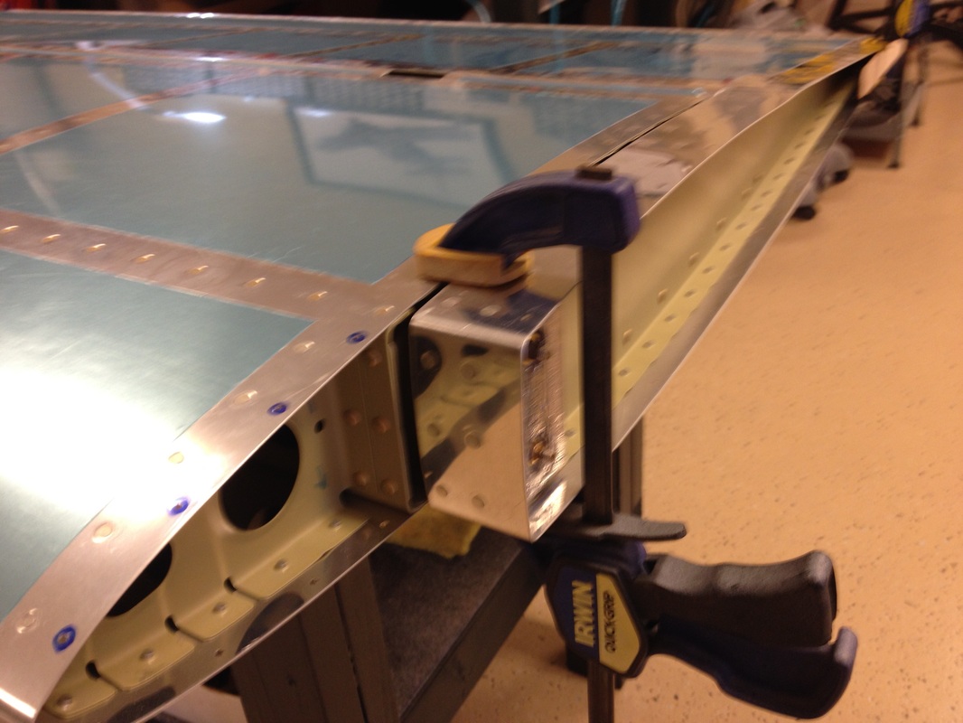
per the manual, clamp the balance arms to stab in trail
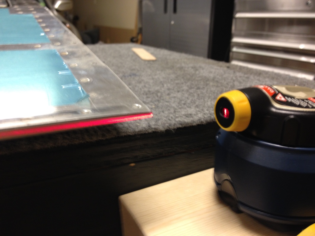
Laser lined up on the elevator trailing edge, right side

Laser at trim tab
laser at trim tab end
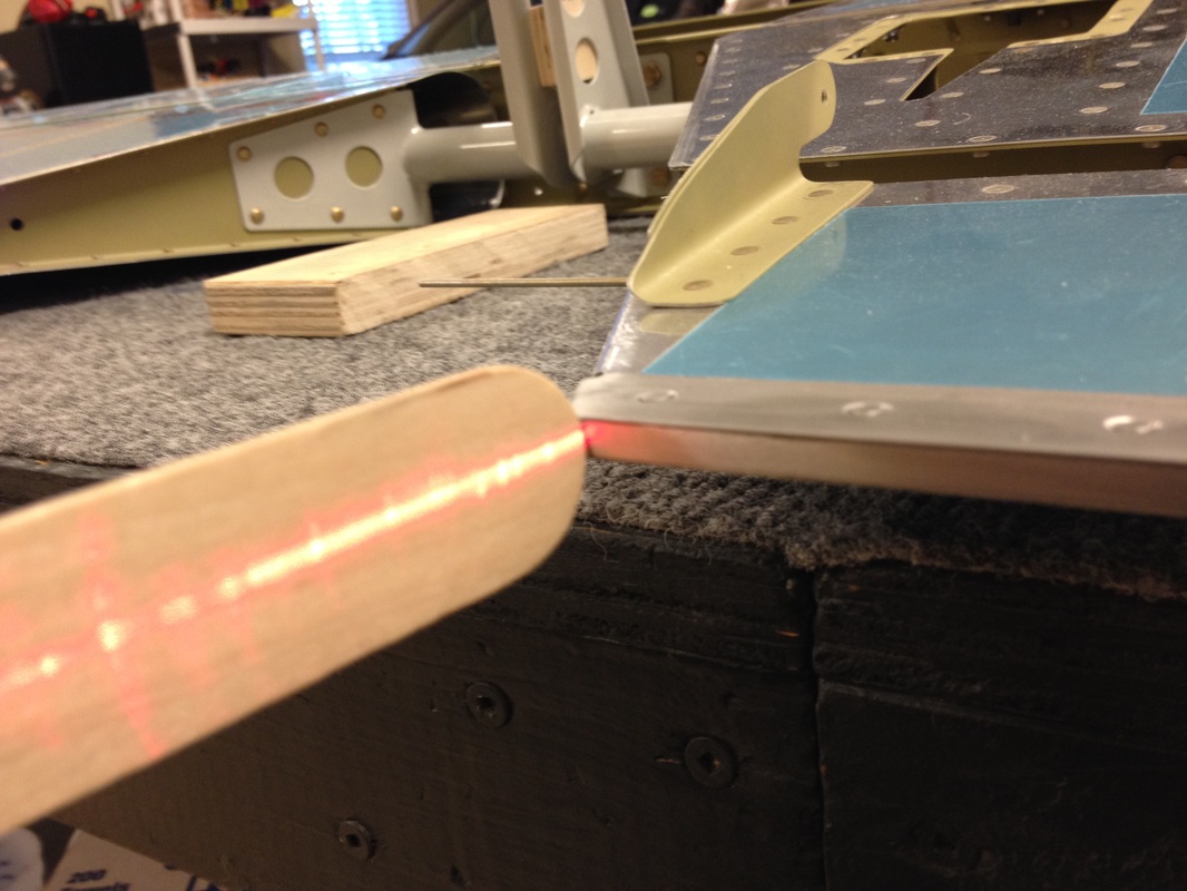
Laser at inside rear edge of elevator on the left side, not the mis alignment here
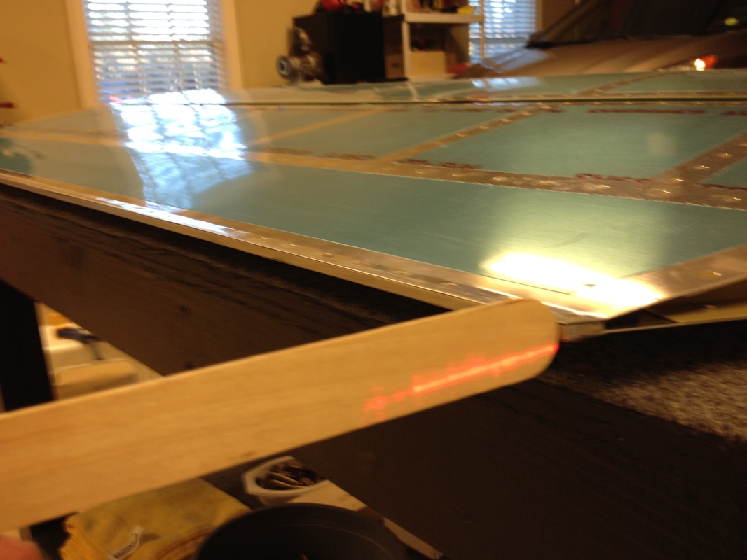
Laser at outside left edge. This may be within tolerances, but we just don't know yet. We did build it on a flat bench, so I'm not quite sure why the inside on the elevator is p over 1/8" unless the rear edge riveting made it move some. The trailing edges are very straight. This makes me think the cumulative punched hole tolerances were enough to allow the deviation from flat. So word back from Van's was the it was within the scope of rounding error. They suggested clamping the trailing edges with boards and then drilling the horn. We massaged it and came close to to eye ball straight.
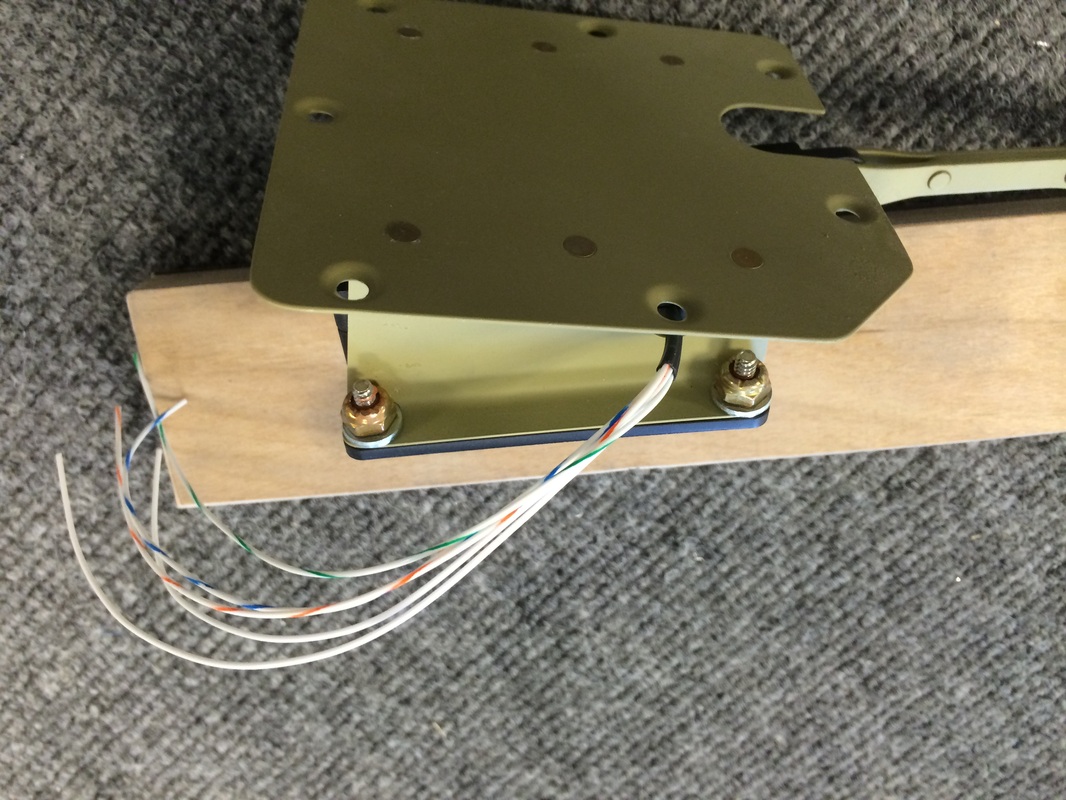
Van's calls for pop rivets here, but I just couldn't do it, so we used 6-32 SS screws with stop nuts and washers which I sanded round on the edge toward the radius of the bracket.
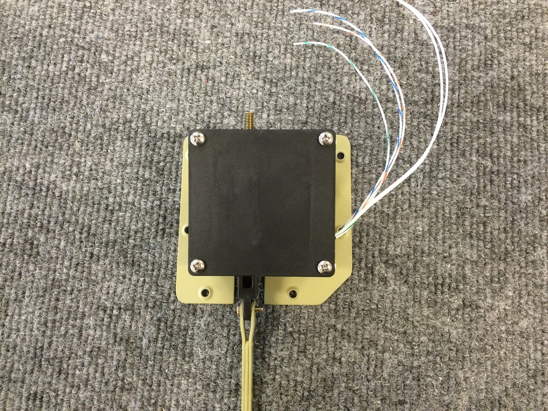
This is a view of the trim motor with the 6/32 x 1/2" screws in place. I think this makes more sense and it will be easy to change if the motor fails. Did it this way in may RV 7A, no issues at all.
Getting the fit to 1/8" per the plans. This is where the artist part come in.

This is filling with Dyna-Delite. Then I sand most of it off and the low parts say filled. I use a block orbital sander to get it close and go to block hand sanding.
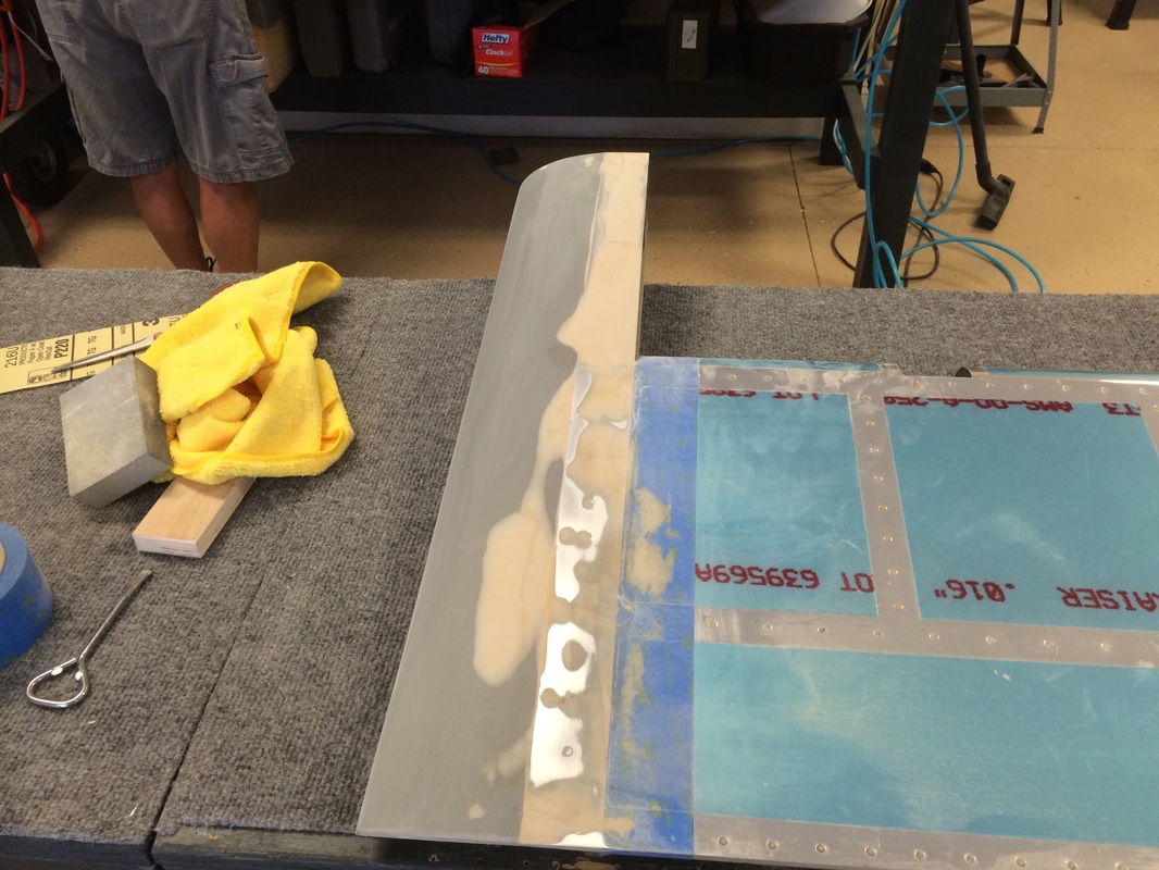
This is what it looks like just before the filler primer.

The elevator tips are finished, just one more thing we won't need to do at final assembly. They turned out the same as my RV 7, which have 5 years now with no issues or cracks.
We used a slight concave surface so the gap looks smaller yet keeps the 1/8" Van's wants in the plans. This also worked out well on the RV 7. I looked at Van's RV 7 at Sun & Fun and they also looked great and was probably a whole lot less trouble than what we did. Oh well, it is the journey not the destination, right?
All done!
