Main Wiring Harness
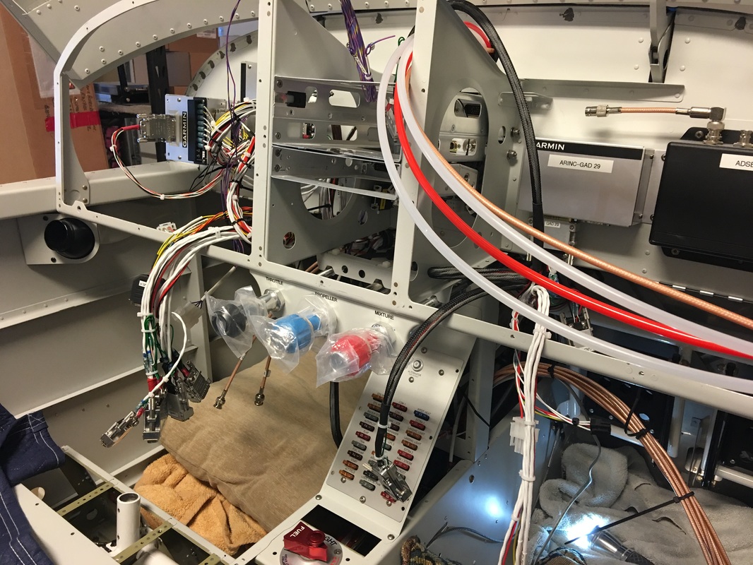
The 8 pictures below is the Van's wiring harness install in the fuselage as one unit. The process we used was to lay it out inside the plane, work the branch runs under the seat and fore and the aft and come back and install split snap bushing into the brackets, ribs and holders. I WOULD NOT INSTALL ANY SNAP BUSHING IN THE PLANE DURING ASSEMBLY IF YOU ARE GOING TO USE VAN'S MAIN HARNESS, BECAUSE THEY WILL HAVE TO BE REMOVED AND SPLIT !


Van's fuse module mounts in this new mount and will make fuses much easier to inspect and replace. It mounts to existing nut plates, but we changed the 3 on the top of the bracket from 6/32 to 8/32 for uniformity.
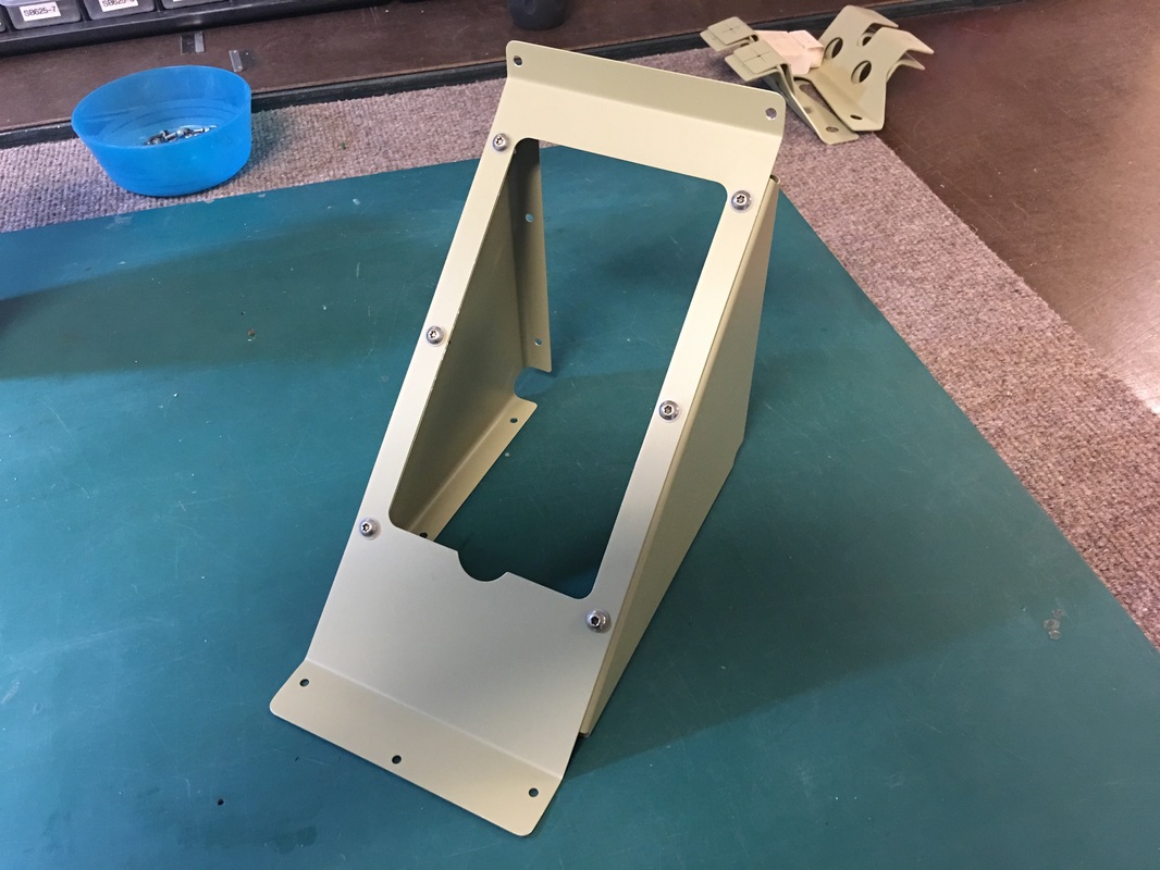
Van's new fuse panel mounting kit.
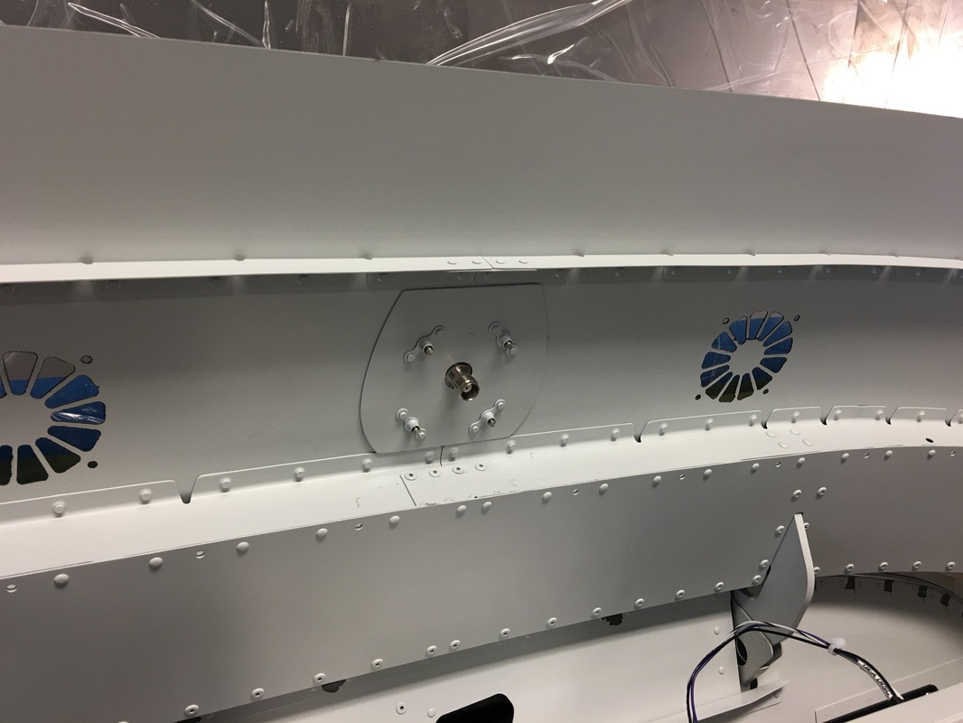
We used plate-nuts for installing the Communication antennas. It makes for easy service, repair and makes for a nice installation
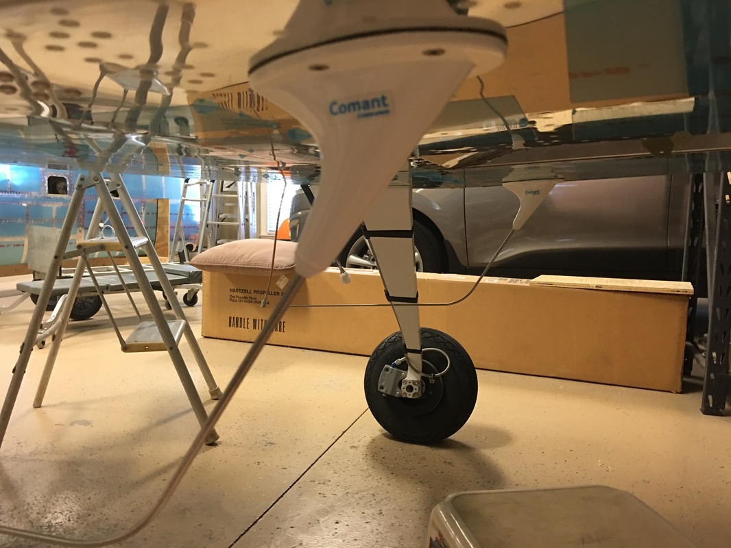
The two Comant com antenna's installed for our two com radios

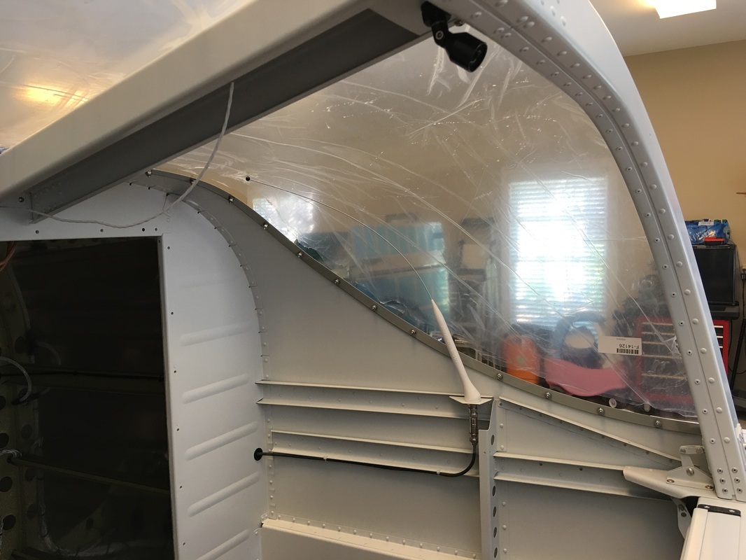
Inside view of the ADS-B antenna. Rafael put a 90 degree BNC connector on it for a very neat installation.
Bad picture , but this is the ADS-B antenna in the tail of the plane, and yes it is the same type of antenna used on the transponder
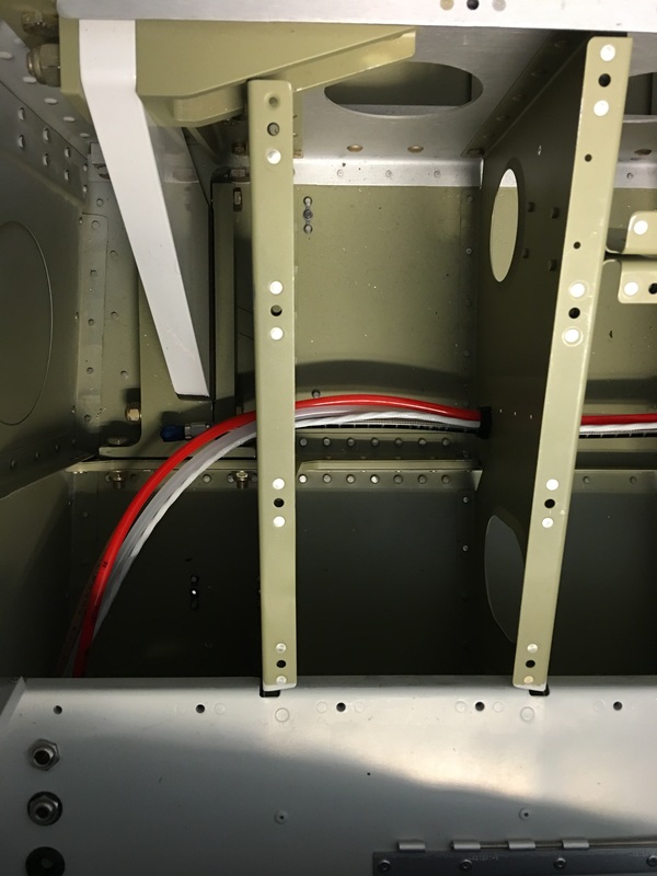
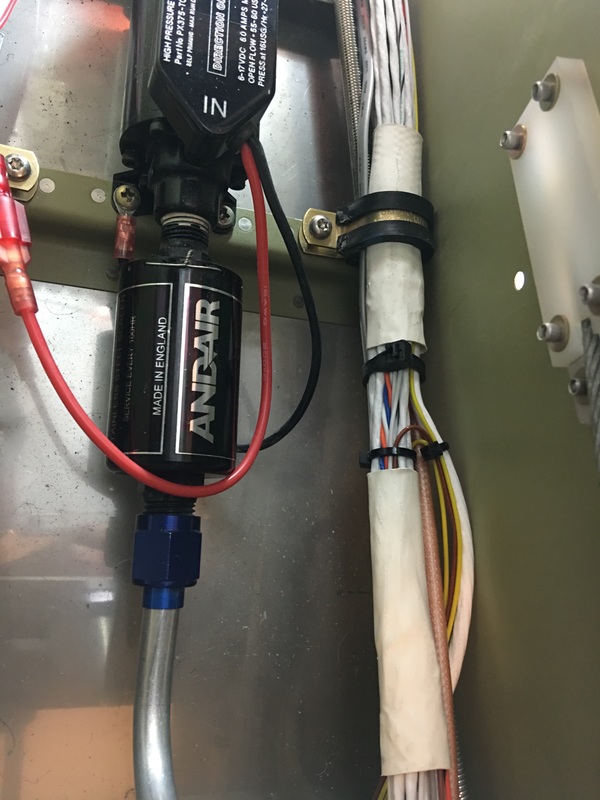
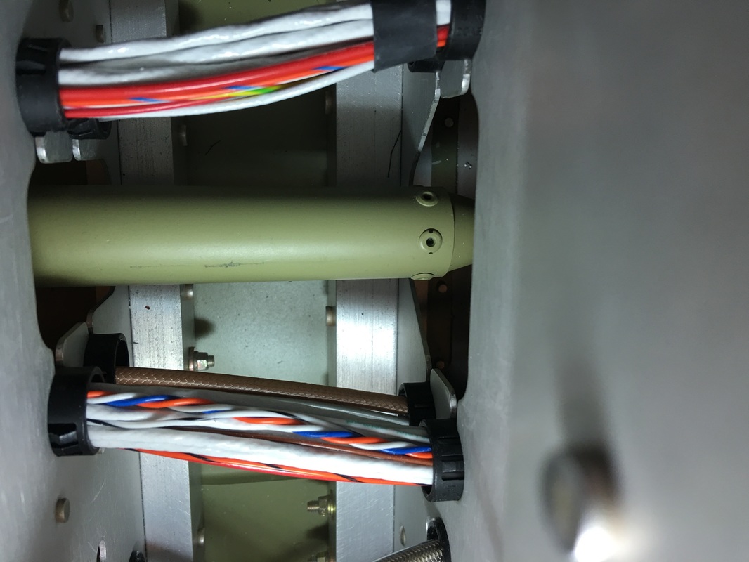
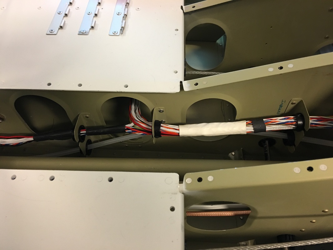
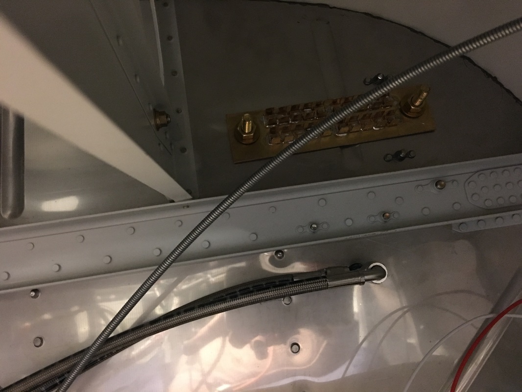
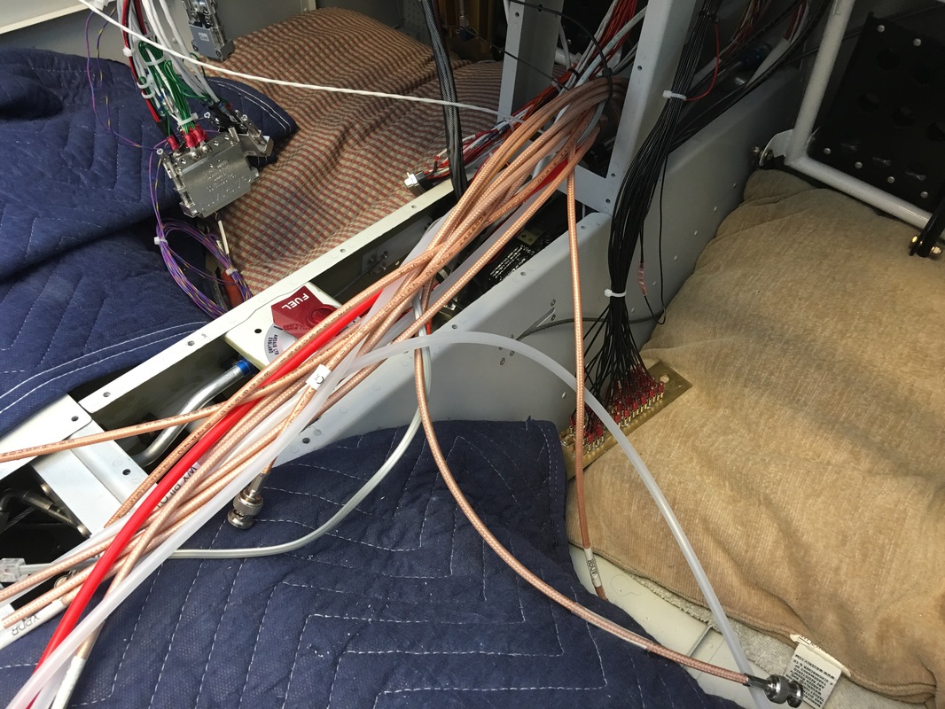
We had to run the pitot and AOA tube through the brake line snaps because there was no more room left in the wing wiring snaps under the seats
|
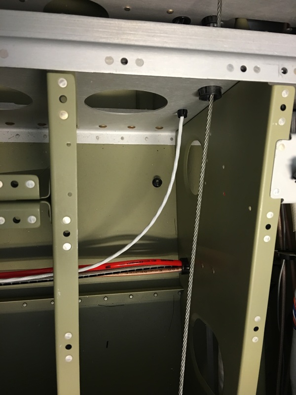
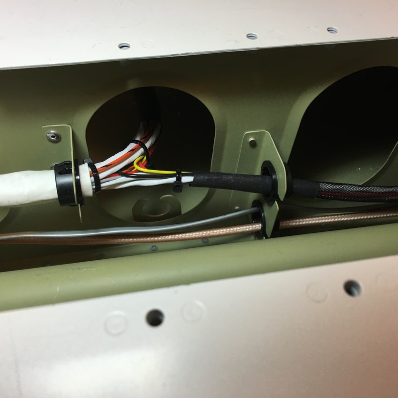
The white shielded wire is for the OAT line.
|
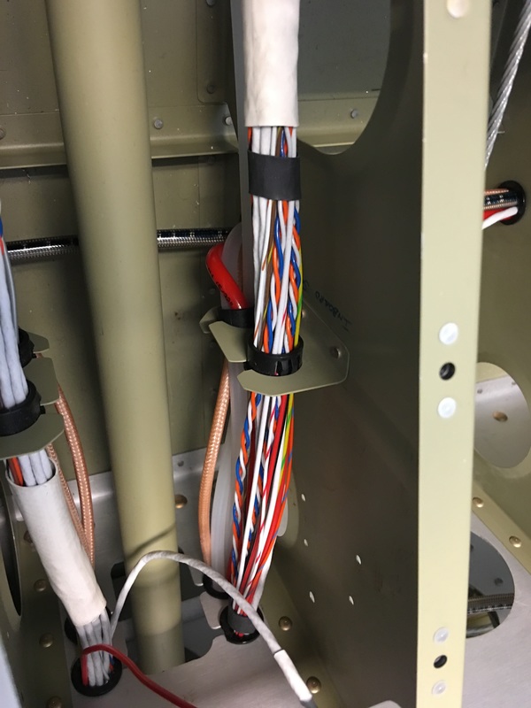
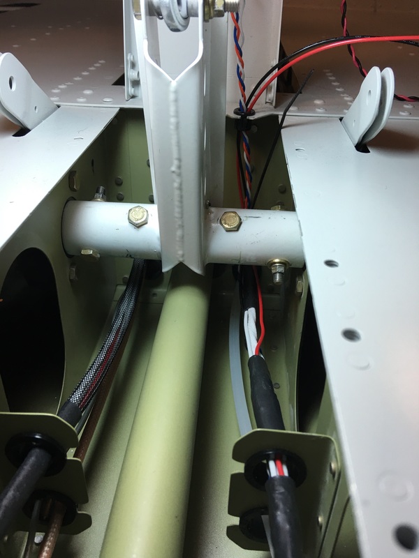
All the wiring runs are getting crowded, but I think we are pretty much done. The is a little room left in the bottom tunnel runs.
|
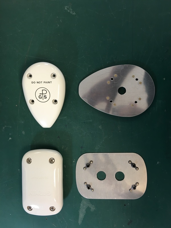
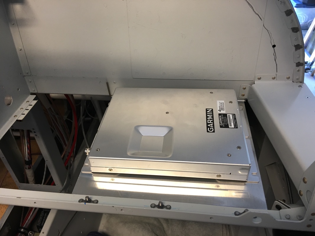
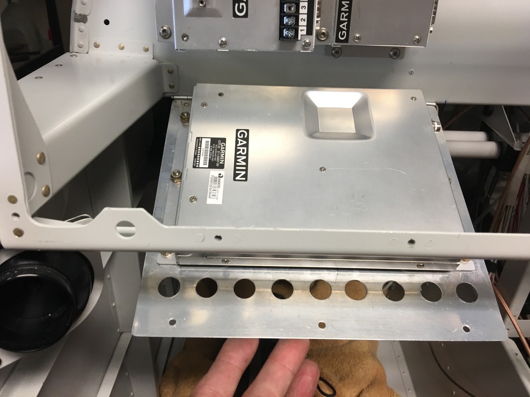
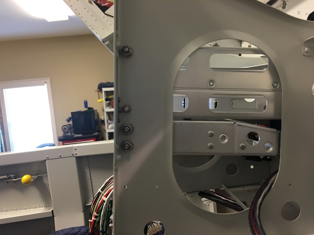
These are the GPS / XM weather brackets we made up to attach the units to the 14's turtle back. We pro-sealed between the surfaces before installing the units
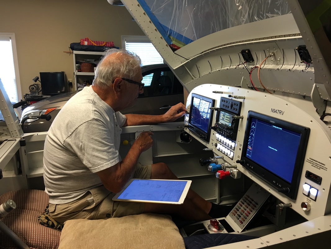
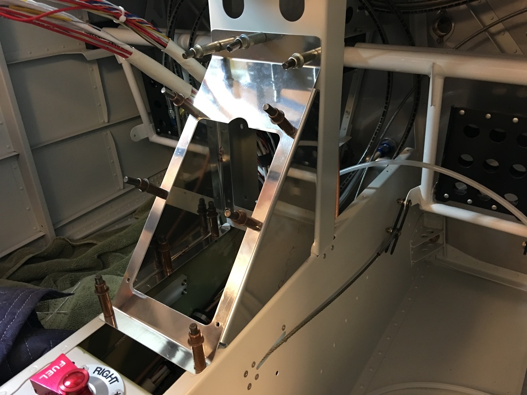
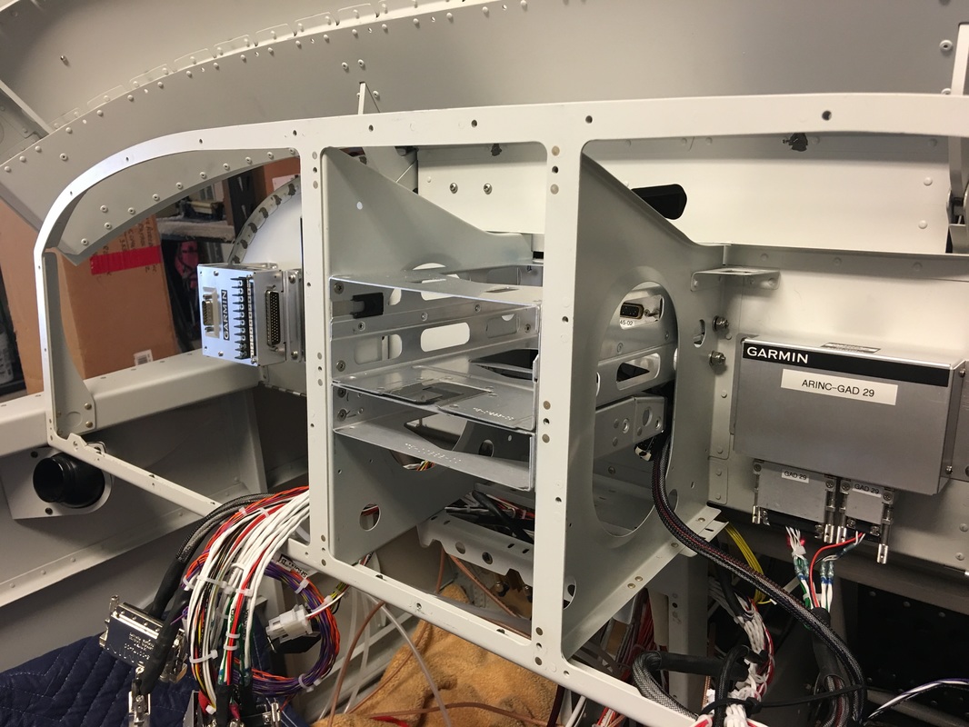
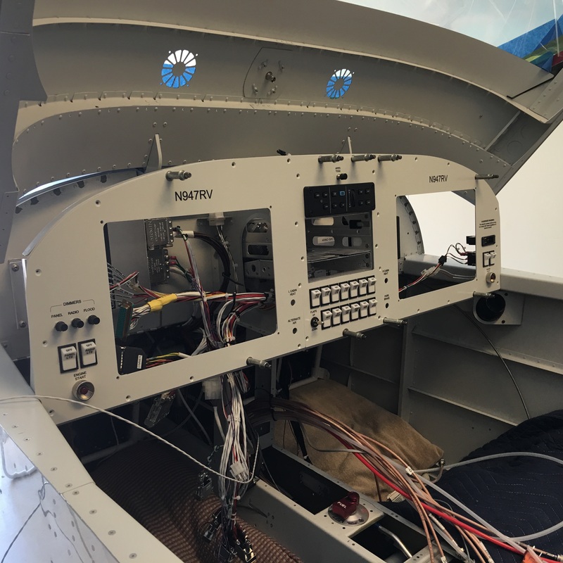
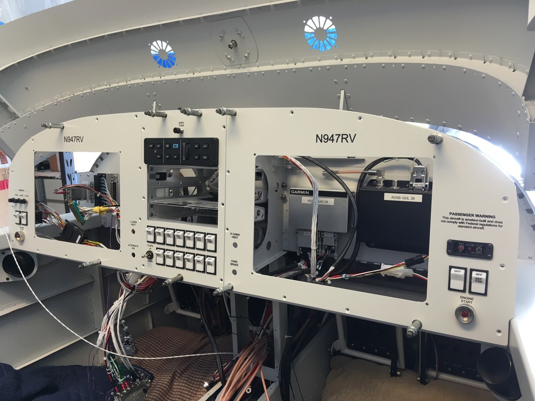
Here we put the panel in place to get an idea of how to fit all the boxes behind the panel.
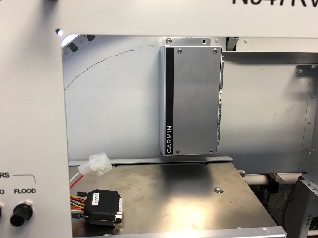
We ended up moving the remote communications radio to the left side after messing with boxes and the transponder when to the right side. We mounted them on hinge panels with three nuts plate-nuts to lock them up in place. Remove the screws the panel opens down for access.
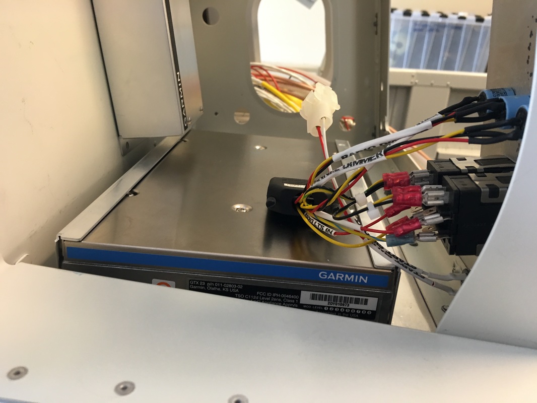
This is the remote transponder which we mounted on a hinged drop down panel to make room for all the other boxes
The EIS brains. There are 4 connectors and large cables that go to the engine compartment for all the sensors. This is the reason for all the room to the right of the box. Pictures later after the cables are installed.

Here the comm radio is on the left side and you can see how the hinge functions.
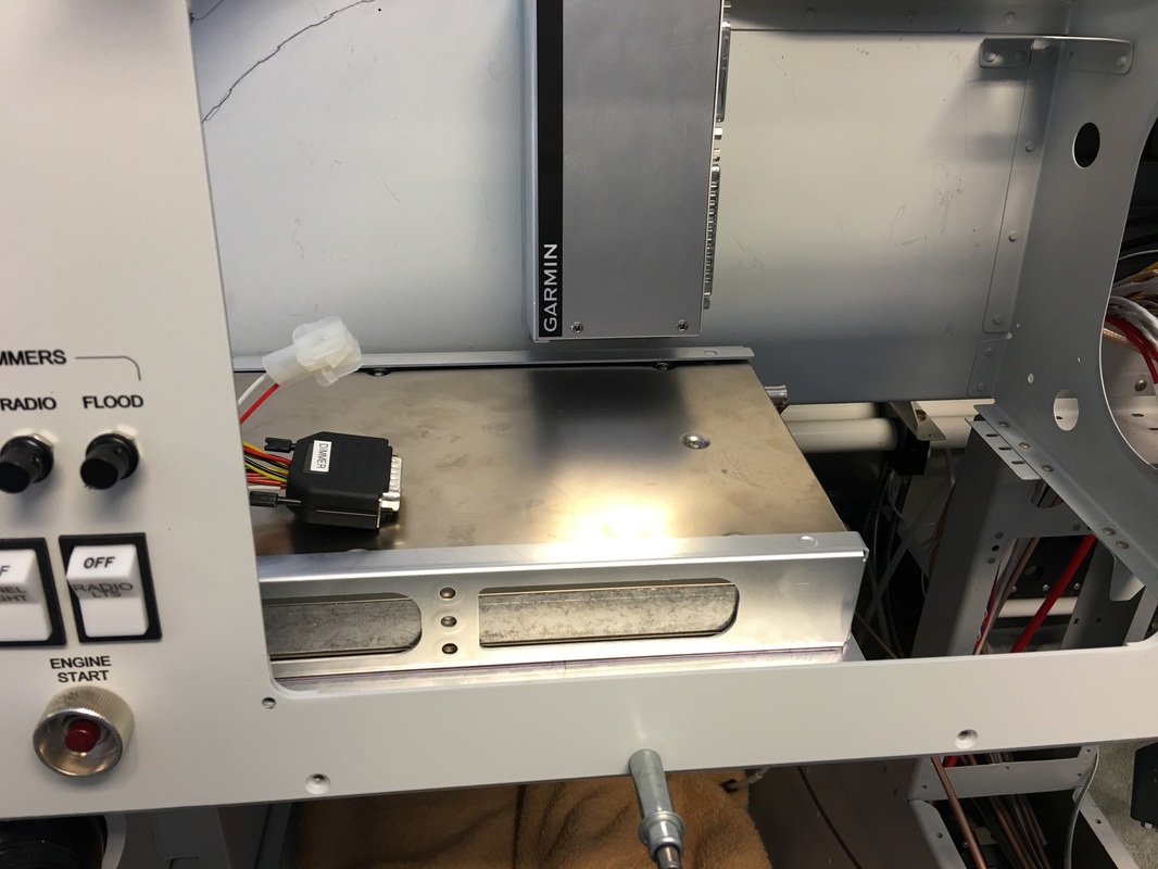
We got the GAD 27 box (flap, lights and trim) mounted to the sub panel, but we had to build an elaborate bracket to bring it off the sub panel 2" so the cable and connector would clear the EIS box.

Remote transponder also mounted on a hinge panel for access. Pull the hinge pin and the unit drops out.
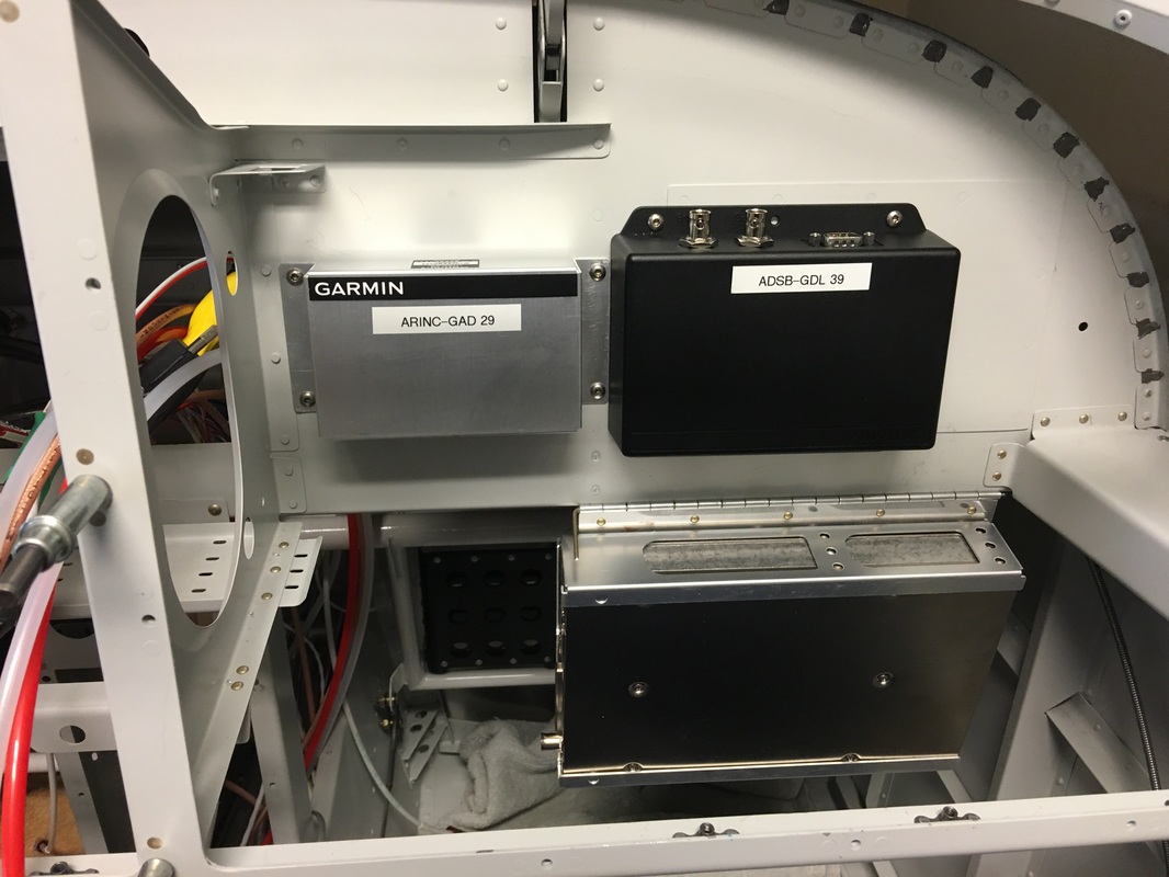
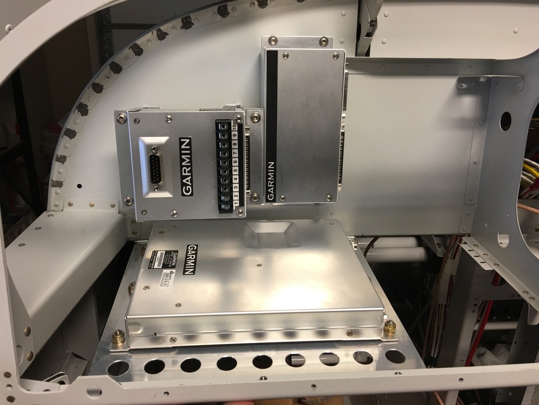
This is the ARINC unit and ADSB boxes with the transponder in the full open/ hanging position

This GAD 27 bracket looks like a kludge and you are right. In defense, the only way to get the wire cables to it without bending them was to elevate the box. It works, its strong and should promote cooling.

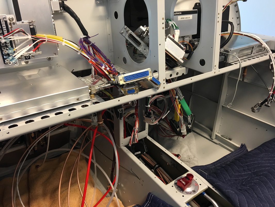
As you can see there is not much room left after all the boxes are in place. This took a lot of planning to get it all in with clearance for the cable connections.
still lots of connections and the all need buzzing out for safety purposes. There were some issues in the cable fro SteinAir with the GAD 27, which is a new box. Rafael worked with Garmin and Steinair to resolve them. It problem was with the PWM lighting circuit and dimers and how they should be connected. The GAD 27 is a new programable box for lighting, flaps and trim connections
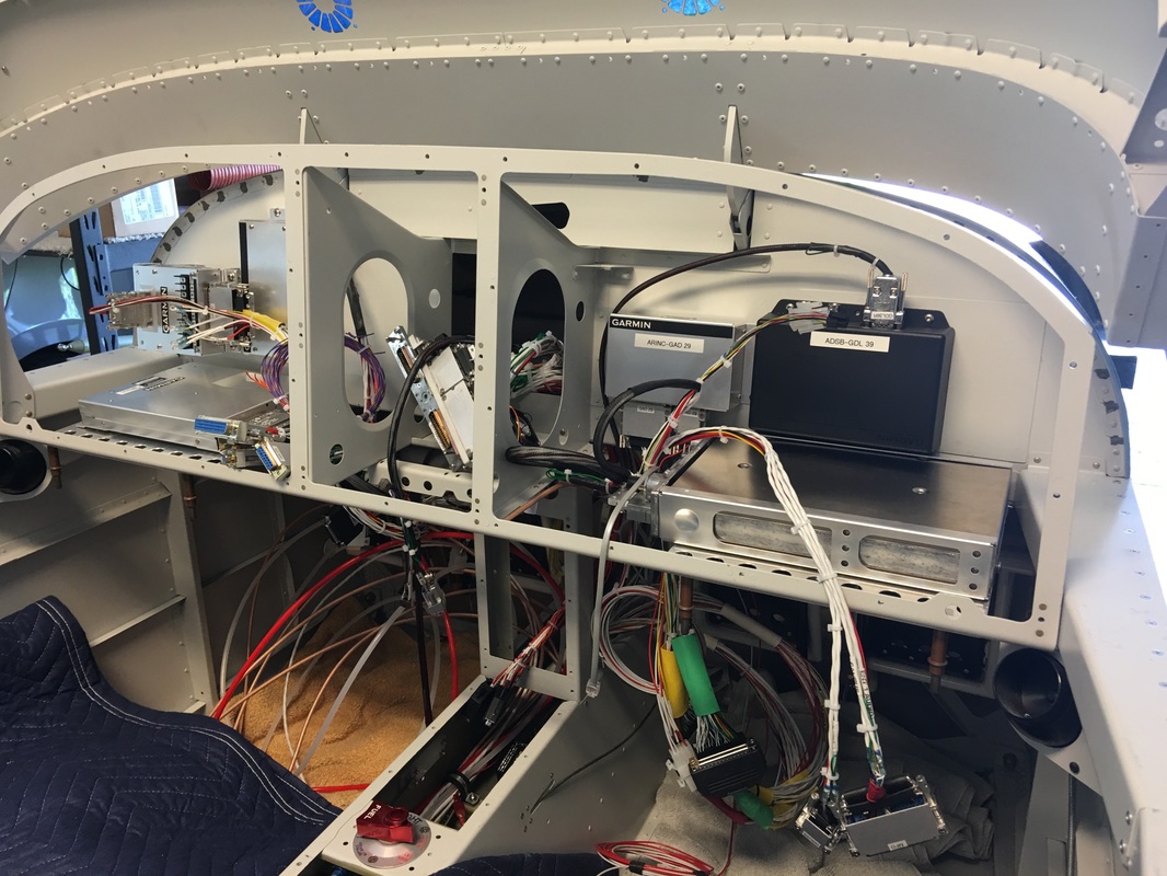
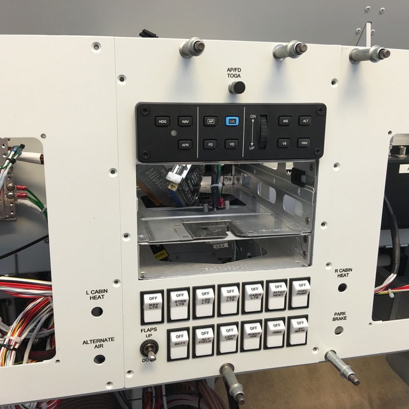
This view is all the boxes mounted except the center stack.

We are replacing the flap switch after talking to Garmin and how it should be wired.
We have a new flap switch on order that will fit, DPDT switch was not required.
We decided to install the main GTN 650 GPS antenna on the glare shield. We already have two on GPS antennas on the fast back and no more room for a third.
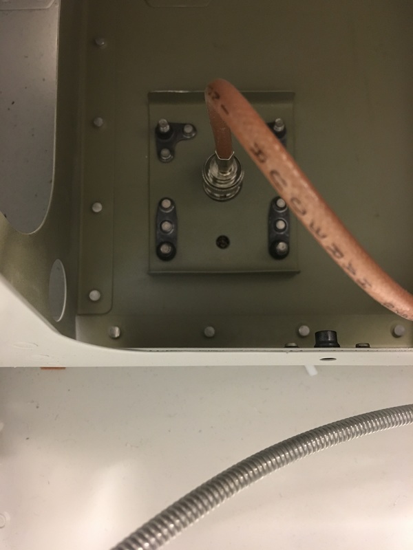
We install the grounding plane in the upper left inside firewall right behind the main grounding strap from the battery. I think this is a pretty ideal location
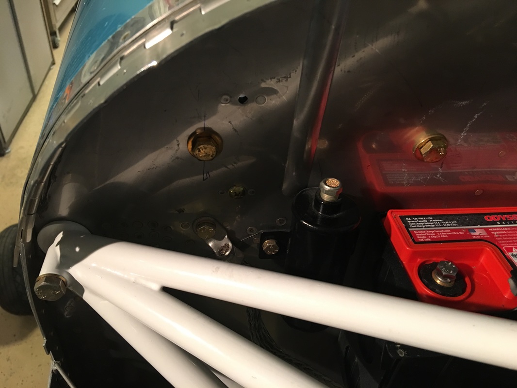
Ground plane bolts through the firewall.
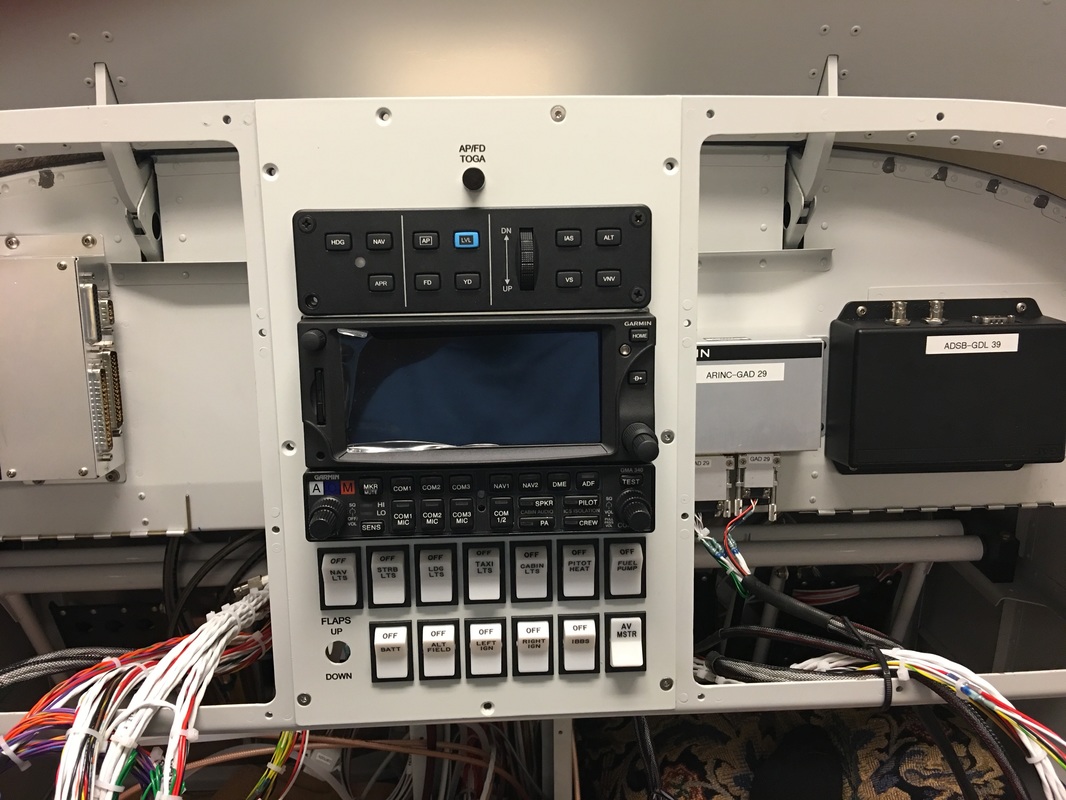
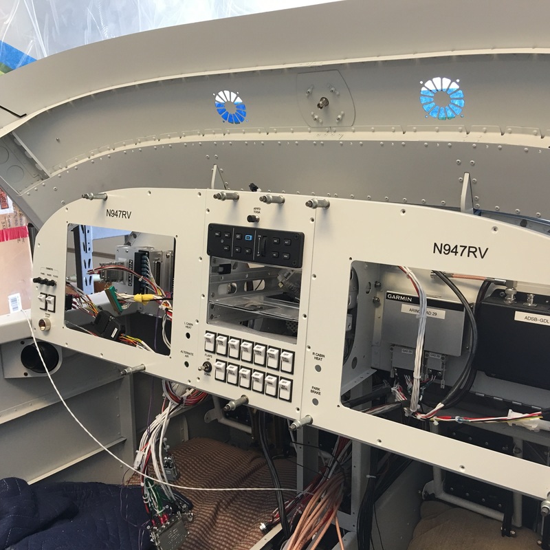
We installed the Garmin GTN 650 and the audio panel chassis, wow, looks simple but it was a real job. We use shims made out of .032 aluminum sheet instead of washers. The washer method is just to hard to get them in place with the side panels in the way.
We had one plate-nut in the way and had to get creative with the hardware. Rafael cut the screw length down, we omitted the washer and use a small stop nut.
It is slowly coming together, but still much to do
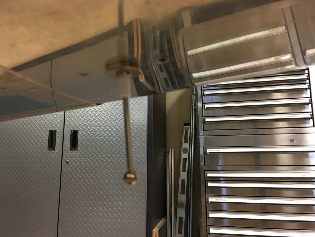
ELT antenna

Map or dome light, what its called also got hooked into the troublesome GAD 27 wiring.
There is still all the antenna coax cables, pitot and static tubes and the fuse panel wiring to be routed and connected