Carl & Rafael's RV 14A Builders Site
  • Home
  • Aiken Airport KAIK
  • Previous Builds
  • Carl's RV 7A
  • Rafael's RV 12
  • About the RV 14
    • RV 14A Specifications
    • RV 14A Performance
  • Work Shop
  • Empennage
    • Kit Delivery
    • Vertical Stabilizer - Sec. 1 thru 6
    • Rudder - Sec. 7
    • Stabilizer - Sec. 8
    • Elevator - Sec. 9
    • Rear Fuselage - Sec. 10 thru 12
  • Wings
    • Kit Delivery
    • Spars - Sec. 13
    • Main Wing Parts - Sec. 14
    • Ribs - Sec. 14
    • Wing Assembly - Sec. 14 Thru 17
    • Fuel Tanks - Sec. 18
    • Bottom Wing Skins - Sec. 20
    • Flaps - Sec. 21
    • Ailerons - Sec. 22
    • Aileron Control System - Sec. 23
    • Wing Tips - Sec. 24
    • Aileron Trim - Optional
  • Fuselage
    • Kit Delivery
    • Mid Fuse Bulkheads - Sec. 25
    • Mid Fuse Lower Structure - Sec. 26
    • Firewall - Sec. 27
    • Fwd Fuse Lower Structure - Sec. 28
    • Fwd Mid Fuse Side Structure - Sec. 29
    • Aft Fuselage Attach - Sec. 30
    • Fuel System - Sec. 31
    • Baggage Area - Sec. 32
    • Interior Painting - End Sec. 32
    • Rudder and Brake Systems - Sec. 33
    • Flap Actuation System - Sec. 34
    • Upper Fwd Fuselage - Sec. 35
    • Aileron & Elevator Systems - Sec. 36
    • Roll Over Structure - Sec. 37
  • Finishing Kit
    • Finishing Kit Delivery
    • Canopy and Window - Sec. 38
    • Seat-backs - Sec. 39
    • Landing Gear and Engine Mount - Sec. 40A
    • Wing Attachment - Sec. 41
    • Miscellanea - Sec. 42
    • Engine & Propeller Delivery
    • Engine Installation - Sec. 43
    • Spinner & Propeller - Sec. 44
    • Cowling - Sec. 45
    • Tricycle Gear Legs & Fairings - Sec. 46A
  • Firewall Forward
    • Engine Specifications
    • Cowl Baffle - Sec. 47
    • Exhaust System - Sec 48
    • Fuel & Oil Systems - Sec. 49
    • Control Cables - Sec. 50
    • Firewall Forward Misc. - Sec. 51
  • Panel & Instrumentation
    • Panel
    • Wiring & Equipment
    • Sensors
    • Avionics
    • Landing Lights - OP52
  • Move to KAIK & Final Ass'y
    • Empennage Installation
    • Wing Installation
    • Odds and Ends
  • Fiberglass & Body work
  • Weight & Balance
  • FAA Inspection & First Flight
  • Phase I & Changes
  • Interiors
  • Paint Design & Painting
    • Scheme Designers
    • Glo Custom
  • RV Builders Forum
  • RV 14 Builder Sites
  • Builder's Location
  • Closing Thoughts
  • Picture Page

Engine Installation:  Sec. 43 November 2, 2015 

The finishing kit drawings for the engine installation came and there were some changes made that created a few problems. The main issue was the clocking for the oil pressure fitting which is under the right upper motor mount. In the past and on most installation instructions the oil AN fitting is clocked down and toward the right wing. Vans changed this to up and toward the left side of the plane.  It is a tighter space but evidently doable. We opted to buy a new hose with a 90 degree fitting rather than removing the engine to follow the plans.  Also note, it is easier to install some of the engine fittings before you mount it on the plane, research this first. We didn't have the plans yet, hence our issues. Rafael had a problem with a few hookup because of working room, but managed to complete Sec. 43, pictures below.
Picture
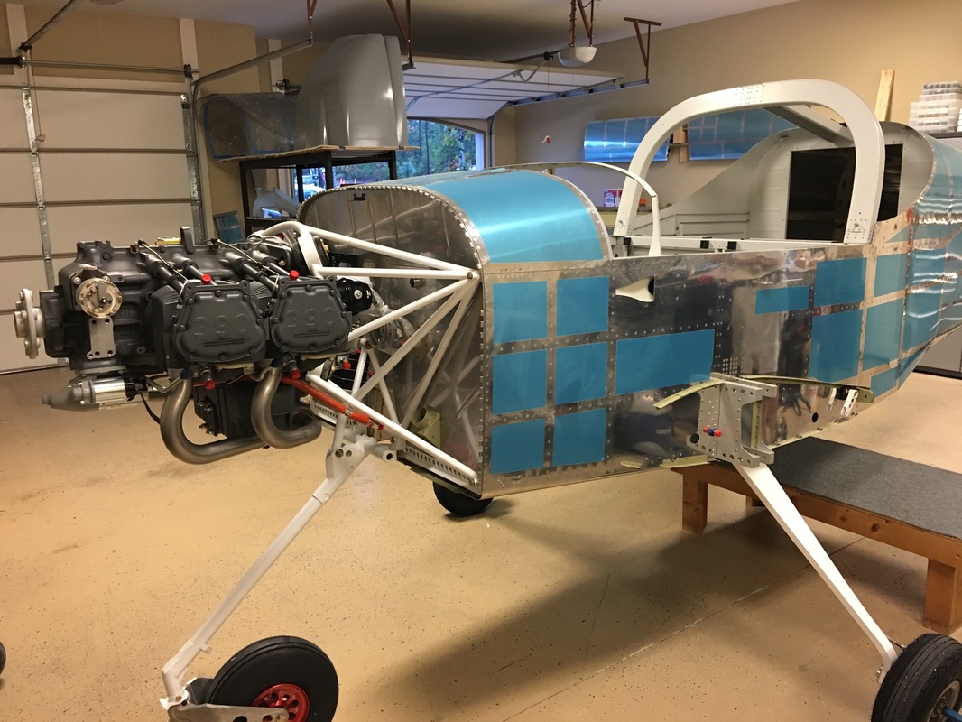
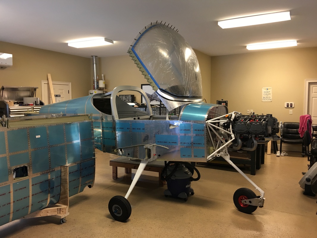
Today was the day to get the engine hung. We ordered the Dynafocal mounts ahead of the finishing kit along with the governor.
Picture
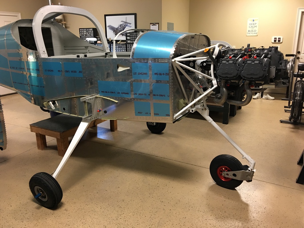
We had Ed Booth ( an extraordinary experimental A&P ) come over to give us a hand and make sure we installed the engine correctly. We planned on 4-6 hours, but it only took about 2 hours. 
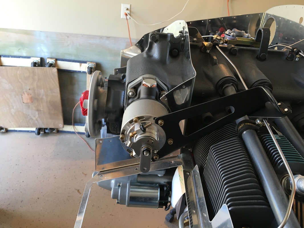
I couldn't believe how well the engine fit into Van's mount with very little persuasion required. When we did the RV 7 it was a whole different story. That installation required mounting the engine to the Dynafocal mount first and then the assembly was mounted to the firewall. The governor was a little bit stubborn to install. The issue was getting the teeth to mesh up with the spline and sliding it into the case properly. Here you do not want to use any brute force. We messed with it and turned the crank back and forth and just when we were getting ready to regroup, it slid right into place.
Picture
We are growing out of Rafa's comfortable garage with HVAC and will need to move to the non-conditioned hanger soon.
Picture
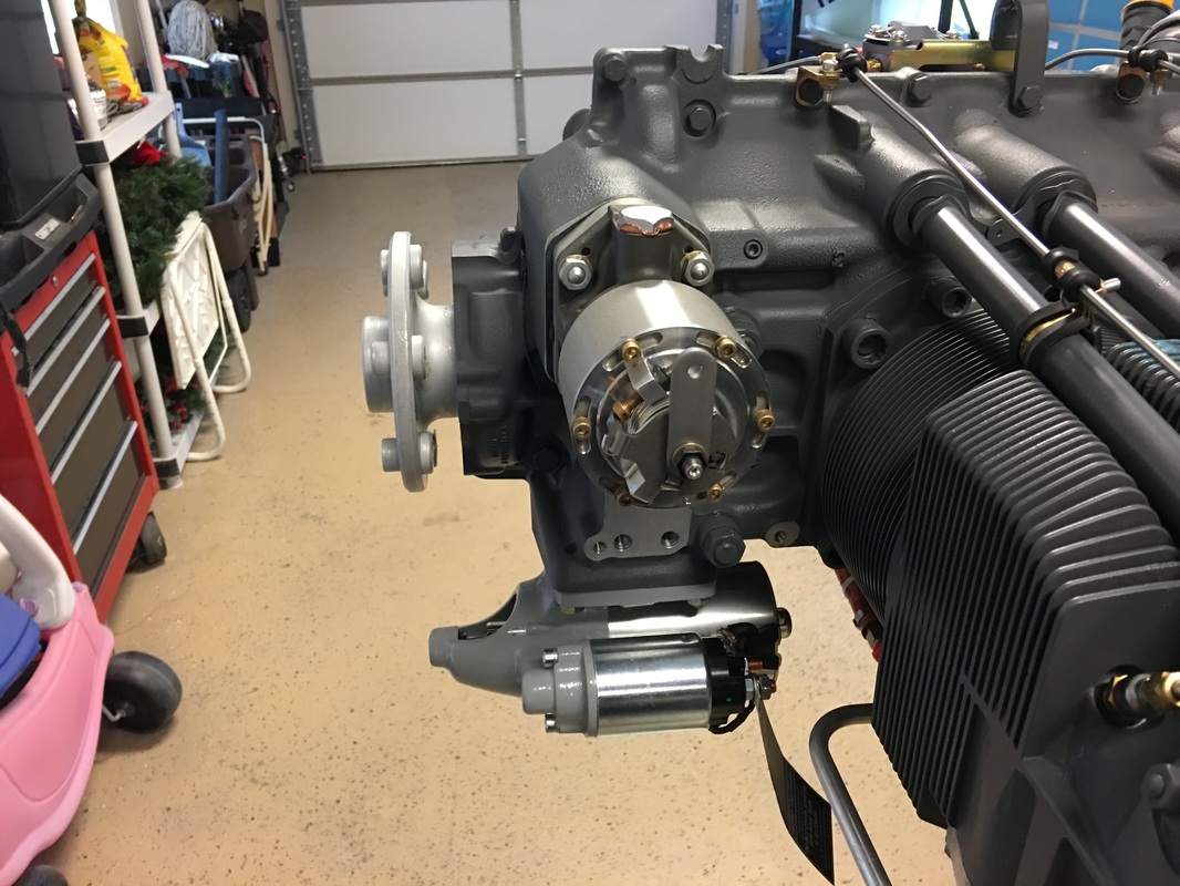
Front mounted governor installation
Picture
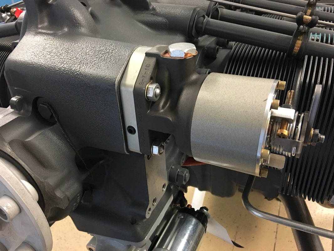
Front view of governor, still needs to clocked properly
Picture
Picture
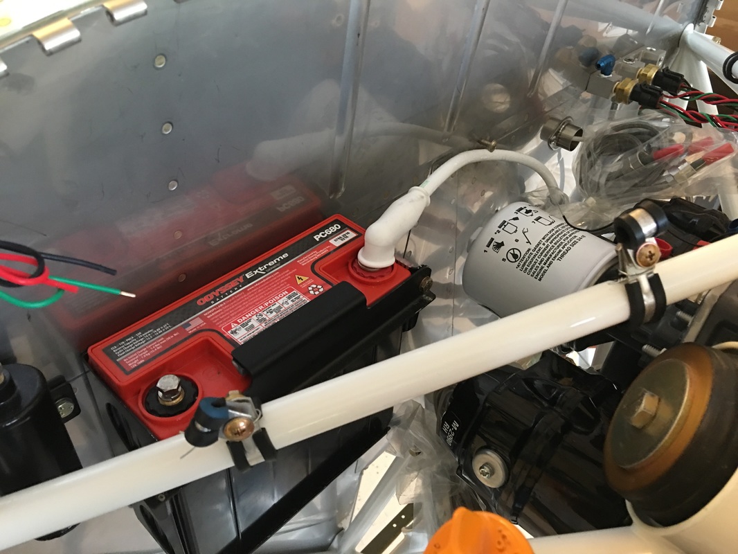
Battery installation
Picture
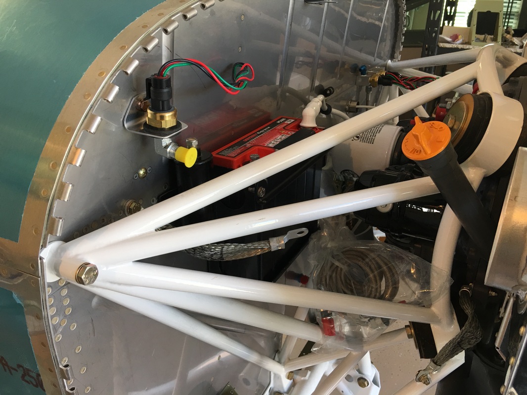
Manifold pressure sensor. We are not sure we like this setup with the sensor mounted in a rubber grommet. We may move it.
Picture
Picture
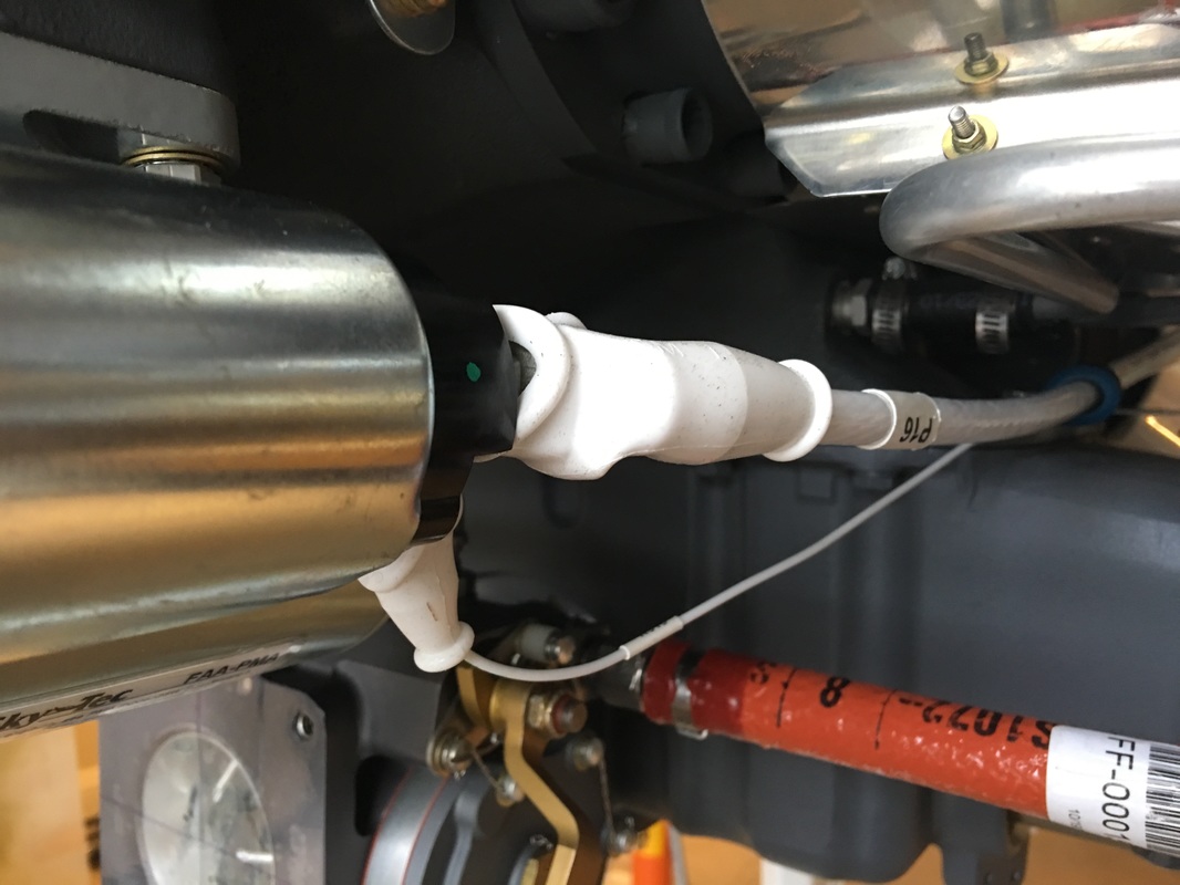
Fuel flow sensor, I would have put it in the tunnel with the fuel pump, but there may be a logical reason for this location, perhaps because it is between the engine pump and the throttle body.
Picture
Starter motor wiring
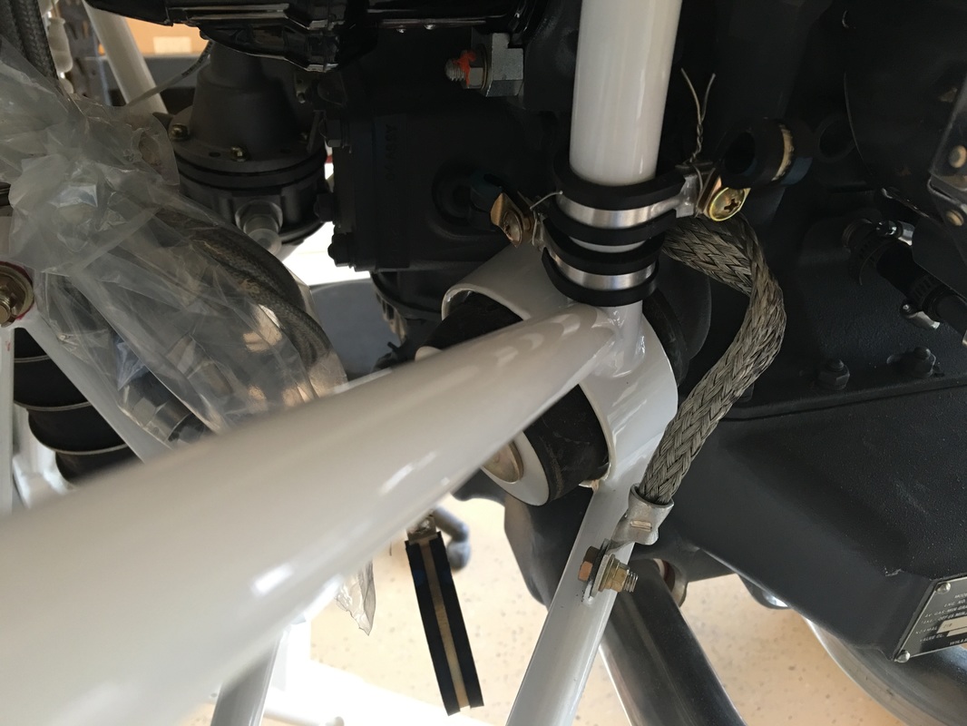
Picture
Motor mount ground
Picture
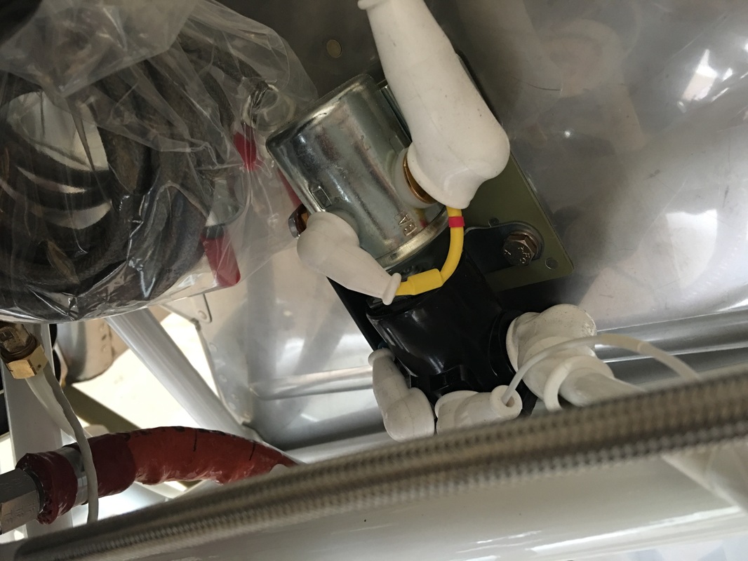
Master relay and starter solenoid installation
Picture
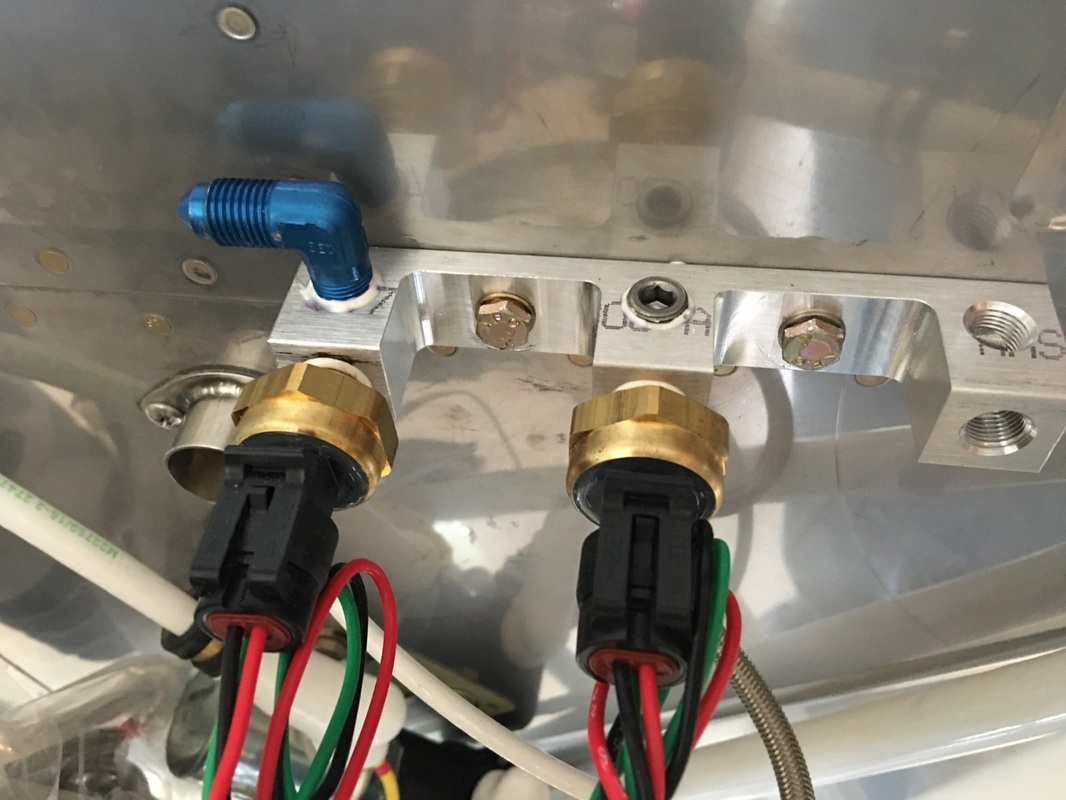
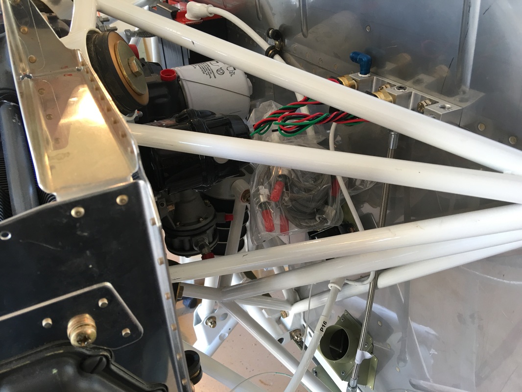
Sensor manifold, we may have one open slot hear for the manifold pressure gauge
Picture
Prop governor with the cable mount attached.
Powered by Create your own unique website with customizable templates.