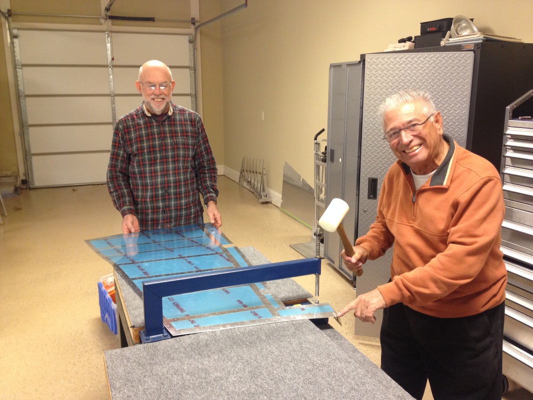
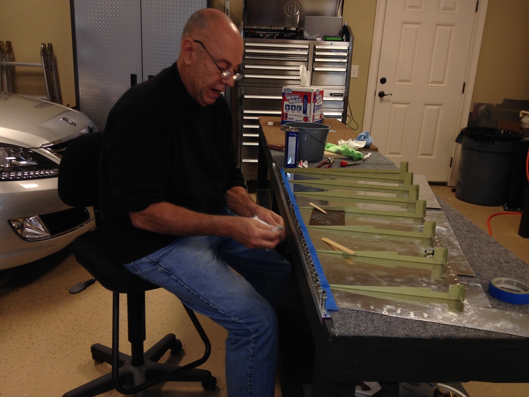
Rafael dimpling the rudder skins with Robin an RV 12 owner that lives in our neighborhood
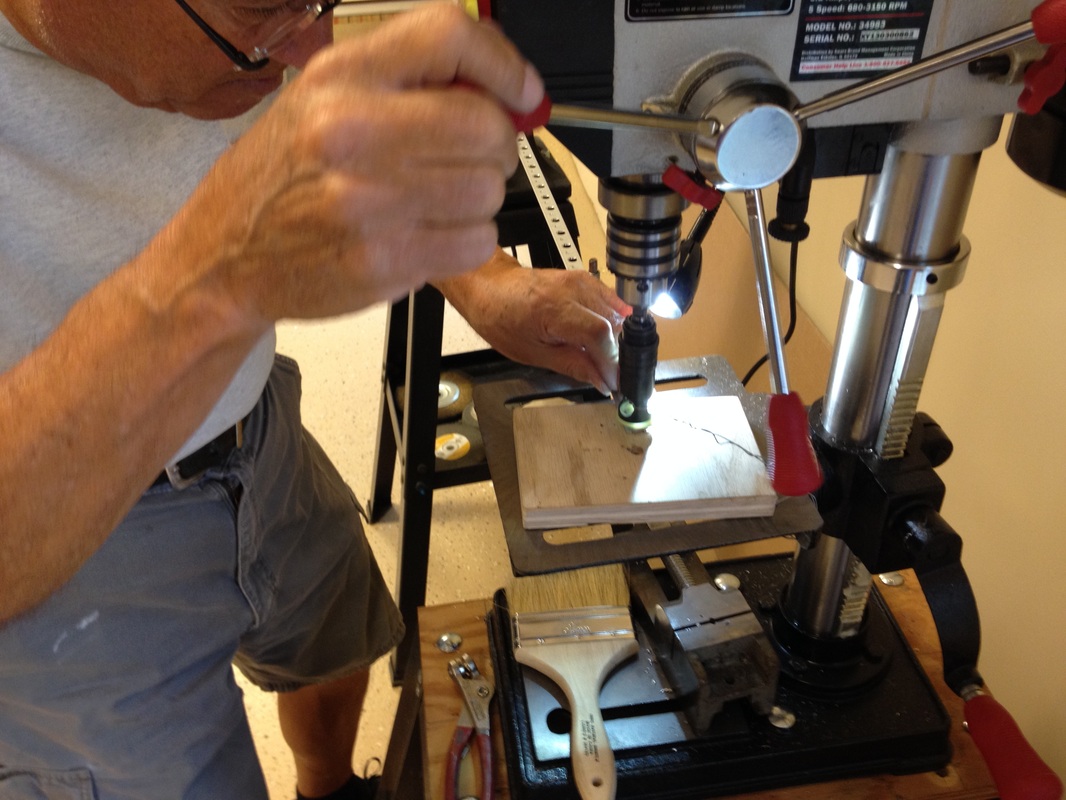
Rafael countersinking the trailing edge V strip
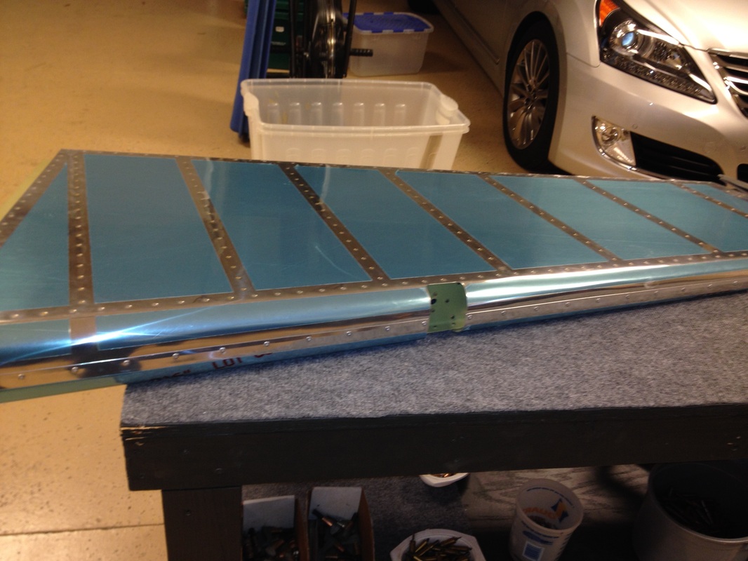
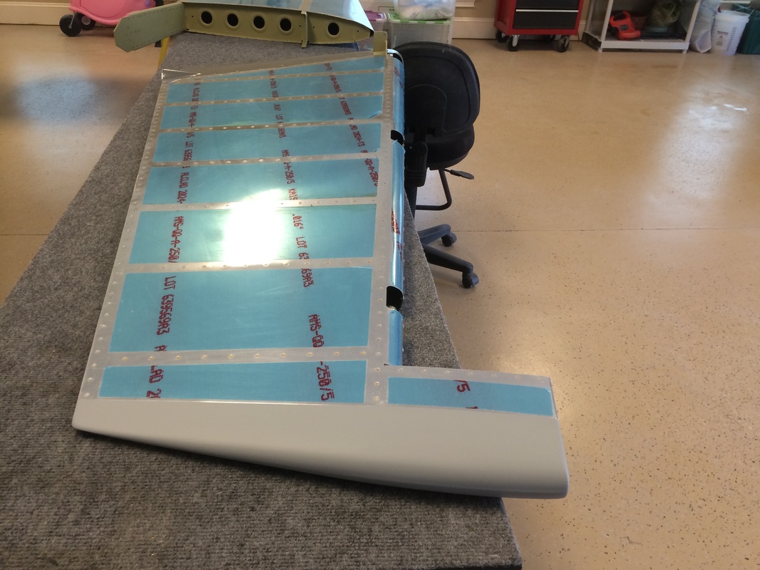
We like to leave the blue film on except where we are working, dimpling or riveting. I did this on the RV 7, and I had no problem removing it after a few years, but it saved many scratches.

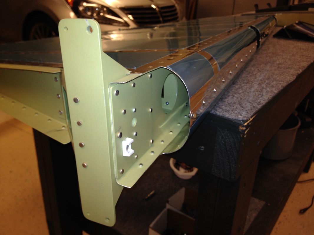
Parts for the vertical stabilizer, rudder and elevator after priming, ready for riveting. We use AKZO and love the toughness. We only do the milled, machined, formed or pressed parts, not the skins. The skins are Alcad and not living on the ocean, we figure that is plenty of protection. Beside we are getting old and know this plane will out live us.
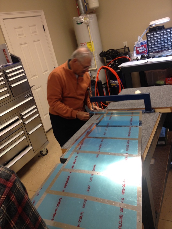
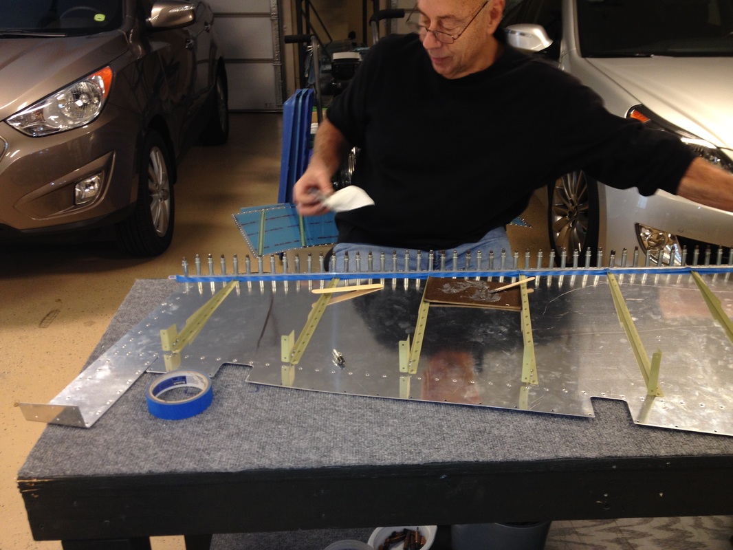
We do they trailing edges a little differently than the construction manual suggests, because I we had great success with this method on the RV 7. We use JB Weld instead of Pro Seal or tape and Cleco the trailing edge to a perfectly straight angle. Every hole! Then do the same when the other skin rolls on. When we get to the riveting method I will show how we do that also.
Use a little tape to keep the extra JB Weld off the skin. A pound saved is a pound earned! Keep em light.

This is a view of the trailing edge clecoed to the aluminum angle and work bench to keep it straight. This worked well on my RV 7A and we decided to use it again on the RV 14. Pro-Seal works well also, but unless you get it thin enough, riveting can pillow the trailing edge.
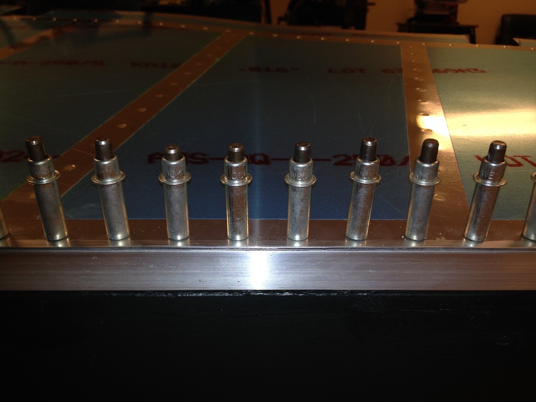
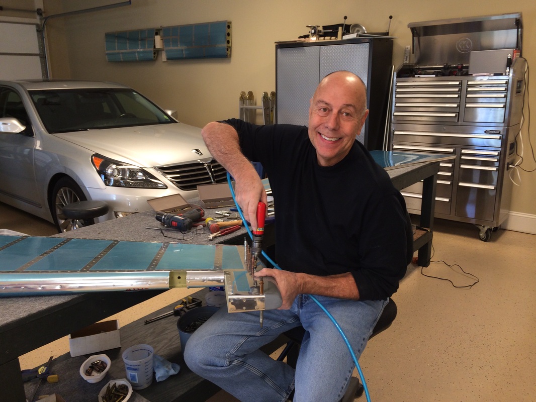
After gluing with JB Weld and wiping off the excess that squeezed out. We let it harden for a day or two, then squeeze the rivets in the trailing edge.
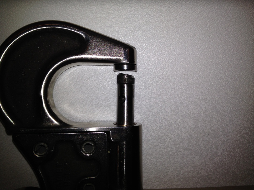
That angle in the rivet die is 7-8 degrees for the final squeeze. We start with a normal flat die and squeeze the rivet to the point it touches the skin on the high side, then finish it carefully with the angled die flush to the skin. I don't try the get the rivet perfectly flush because you can put a smiley in the skin, but we get it within a whisker.
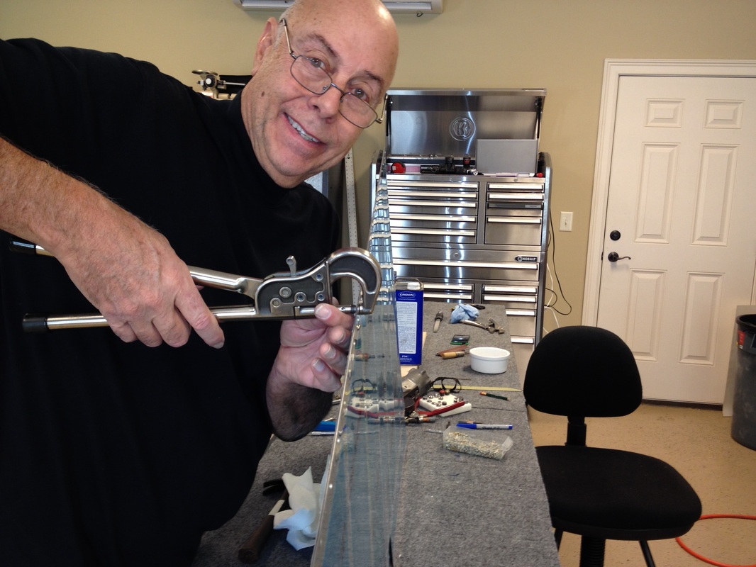
On the rudder trailing edge, I reverse every rivet and squeeze back and forth every ten rivets sequentially. This does not put too much stress on any point and keeps the edge straight. The epoxy helps a lot, but it can break away if you go at any rivet too much at one time. I take my time and listen to the squeeze, and monitor the trailing edge to make sure it is not taking on a curve. Our trailing edges are straight as a ruler. Try it, you may like the process.

Here you can see two adjacent rivets. One is the manufactured head, the other is the shop head. They don't look very different except the manufactured head is slightly smaller.
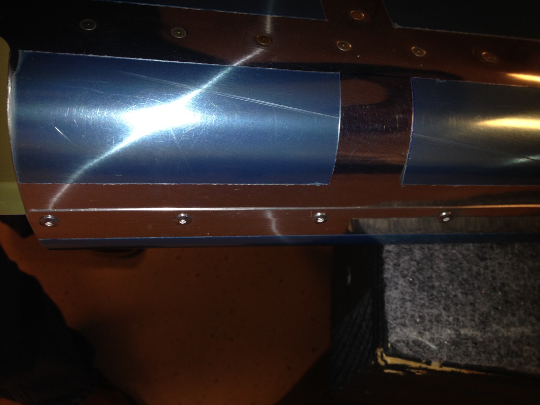
The rolled leading edge of the rudder, I will show how we did it in the elevator section. We did not come up with this technique but got it off VAF from wise builders before us.
Rudder done except fiberglass tip, stay tuned>
Since it is so incredibly cold outside and we couldn't prime, I started working on fitting the rudder top and bottom fiberglass fairings. This one of those hand fit jobs, with a little sanding here and there and tweaking the rudder ribs to facilitate the fit. Going slow and a kettle bit at a time pays dividends here.
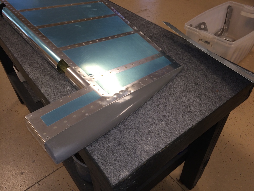
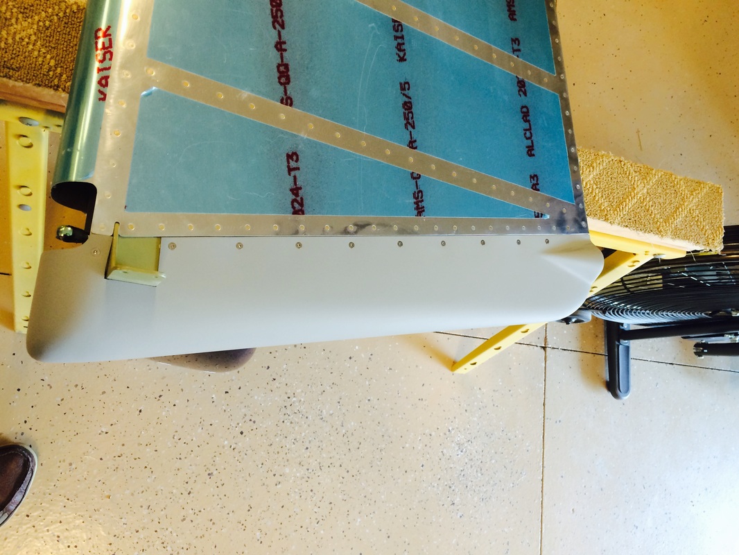
Rudder fiberglass tip pop riveted in place. The fit was good and I was about ready to give Van's an attaboy, but the halves of the fairing were bonded unevenly at the trailing edge. This will require considerable body work before painting. Nothing new, all the tips need some help, but I was thinking the fiberglass parts have improved so much from the RV 7 kit, we have reached nirvana, but it was not to be.
The bottom fit better then the top, although it is quite tricky to cut it properly. This is another place where taking your time and sneaking up on the fit around the rudder horn pays off in a quality job. Next set is drilling attachments and nut plates. Other than eating fiberglass dust, this is a fun job.
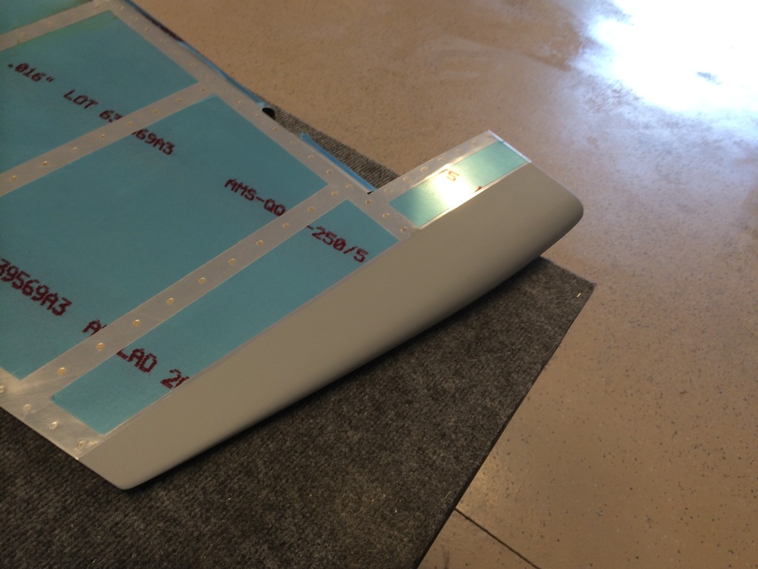
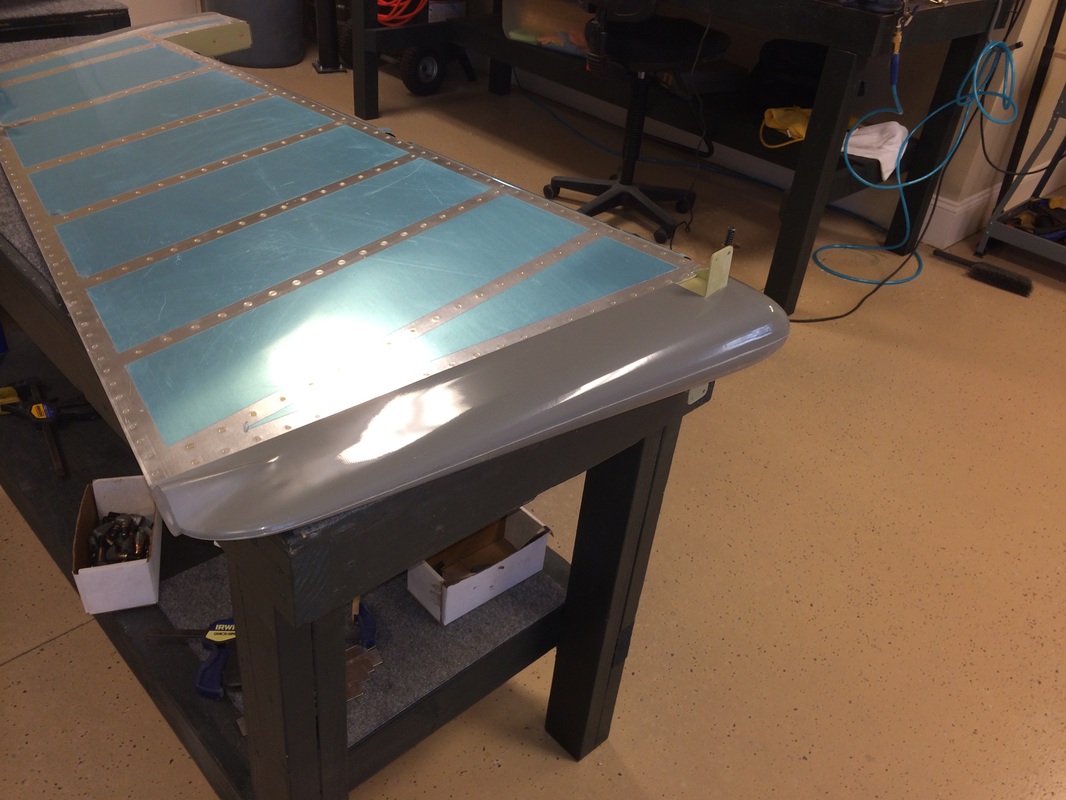
Tip of the rudder after mucho body work, but it is all worth it it the end.
Top view of the rudder ready for the painter.
The rudder bottom fairing complete. We added 2 plate nuts in front of the horn to keep the front down tight, may be overkill, but it just seemed they were needed no matter how we shaped the flange on the spar.
