Carl & Rafael's RV 14A Builders Site
  • Home
  • Aiken Airport KAIK
  • Previous Builds
  • Carl's RV 7A
  • Rafael's RV 12
  • About the RV 14
    • RV 14A Specifications
    • RV 14A Performance
  • Work Shop
  • Empennage
    • Kit Delivery
    • Vertical Stabilizer - Sec. 1 thru 6
    • Rudder - Sec. 7
    • Stabilizer - Sec. 8
    • Elevator - Sec. 9
    • Rear Fuselage - Sec. 10 thru 12
  • Wings
    • Kit Delivery
    • Spars - Sec. 13
    • Main Wing Parts - Sec. 14
    • Ribs - Sec. 14
    • Wing Assembly - Sec. 14 Thru 17
    • Fuel Tanks - Sec. 18
    • Bottom Wing Skins - Sec. 20
    • Flaps - Sec. 21
    • Ailerons - Sec. 22
    • Aileron Control System - Sec. 23
    • Wing Tips - Sec. 24
    • Aileron Trim - Optional
  • Fuselage
    • Kit Delivery
    • Mid Fuse Bulkheads - Sec. 25
    • Mid Fuse Lower Structure - Sec. 26
    • Firewall - Sec. 27
    • Fwd Fuse Lower Structure - Sec. 28
    • Fwd Mid Fuse Side Structure - Sec. 29
    • Aft Fuselage Attach - Sec. 30
    • Fuel System - Sec. 31
    • Baggage Area - Sec. 32
    • Interior Painting - End Sec. 32
    • Rudder and Brake Systems - Sec. 33
    • Flap Actuation System - Sec. 34
    • Upper Fwd Fuselage - Sec. 35
    • Aileron & Elevator Systems - Sec. 36
    • Roll Over Structure - Sec. 37
  • Finishing Kit
    • Finishing Kit Delivery
    • Canopy and Window - Sec. 38
    • Seat-backs - Sec. 39
    • Landing Gear and Engine Mount - Sec. 40A
    • Wing Attachment - Sec. 41
    • Miscellanea - Sec. 42
    • Engine & Propeller Delivery
    • Engine Installation - Sec. 43
    • Spinner & Propeller - Sec. 44
    • Cowling - Sec. 45
    • Tricycle Gear Legs & Fairings - Sec. 46A
  • Firewall Forward
    • Engine Specifications
    • Cowl Baffle - Sec. 47
    • Exhaust System - Sec 48
    • Fuel & Oil Systems - Sec. 49
    • Control Cables - Sec. 50
    • Firewall Forward Misc. - Sec. 51
  • Panel & Instrumentation
    • Panel
    • Wiring & Equipment
    • Sensors
    • Avionics
    • Landing Lights - OP52
  • Move to KAIK & Final Ass'y
    • Empennage Installation
    • Wing Installation
    • Odds and Ends
  • Fiberglass & Body work
  • Weight & Balance
  • FAA Inspection & First Flight
  • Phase I & Changes
  • Interiors
  • Paint Design & Painting
    • Scheme Designers
    • Glo Custom
  • RV Builders Forum
  • RV 14 Builder Sites
  • Builder's Location
  • Closing Thoughts
  • Picture Page

Tricycle Gear Legs and Fairings - Section 46A

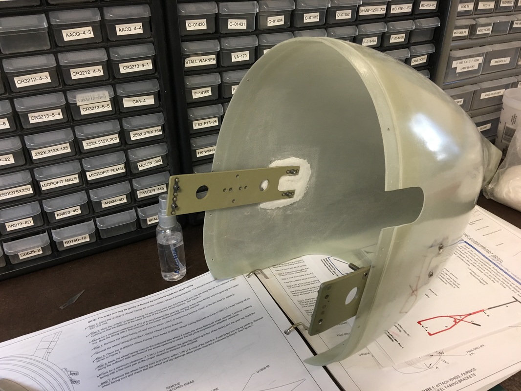
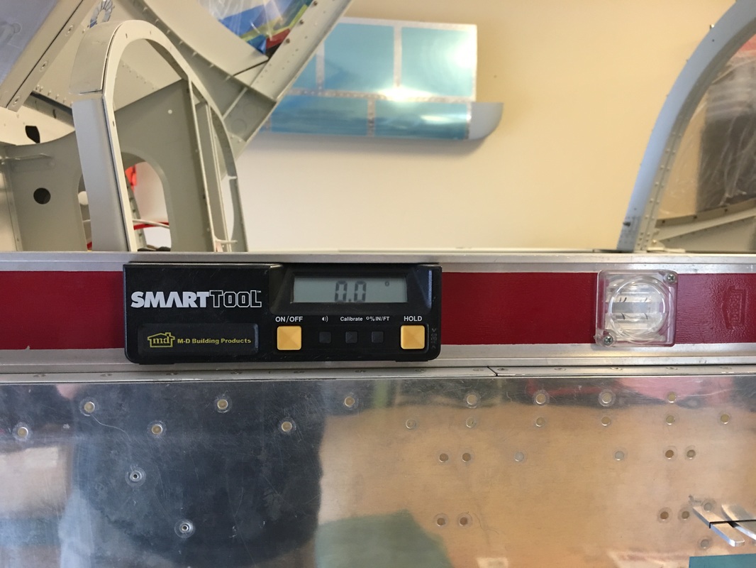
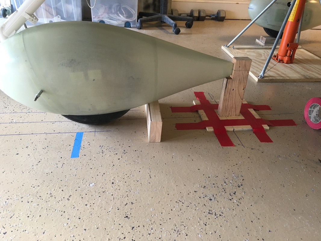
Fiberglass and I just don't get along very well. It always feels like I need to make multiple attempts to get it where I believe it will hold up to the rigors of flight & landings.  Wheel fairings are just a pain in the butt to get them fitting properly, at the right angle and parallel to the flight  stream and the longerons.  Also the attachment points seem inadequate without some beefing up IMO.  I tried using the marked screw points in the main wheel pants, only to have one end up  1 inch higher than the other.  As you can see below, I tried the flox mounting method, but felt it added little strength where the screws attach them to the mounts.  So I went back to the method I used on the RV 7 and added 6 layers of 9oz fiber glass cloth in each screw location. This made the fiber glass at least 1/8" thick there and tapered out the glass with peel ply.  We put some chalk lines on the floor and then re-installed the them once they were in the right location.  It turns out the suggested hole locations were not off by much, but enough to make over a 1" difference at the trailing edge between them. 
Picture
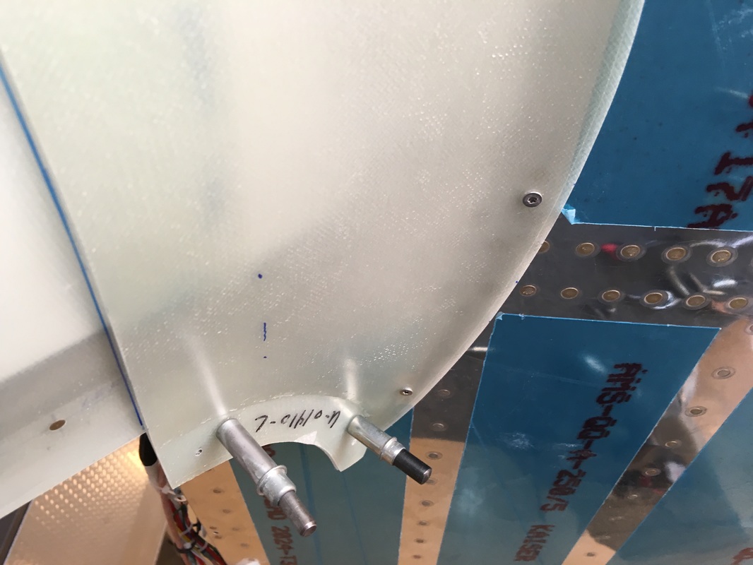
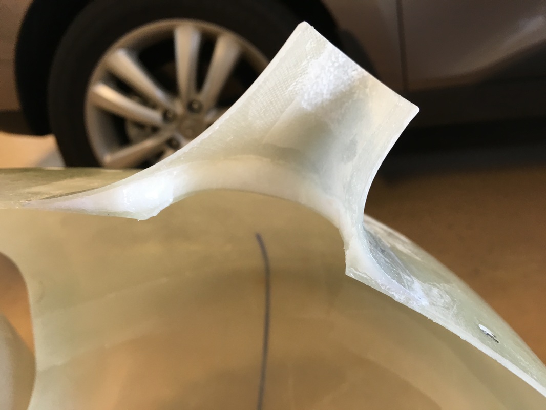
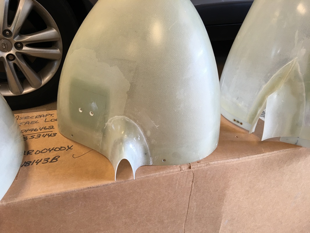
This is the flox method, even with a lightly attached screw, there was not enough material to add much thickness at the attach points
Picture
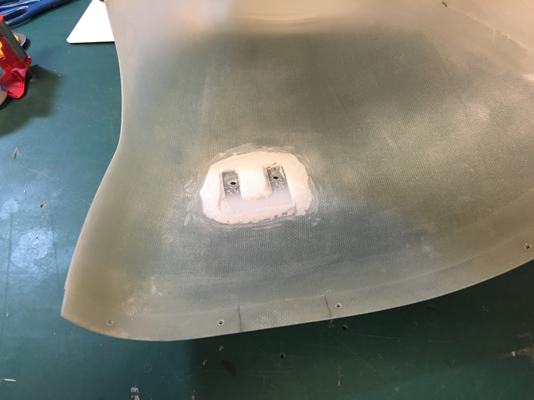
First attempt using the flox method.
Picture
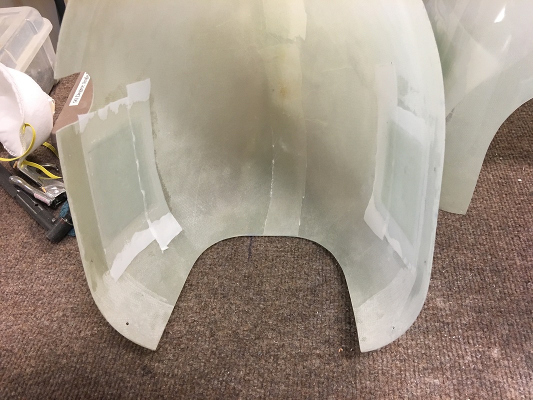
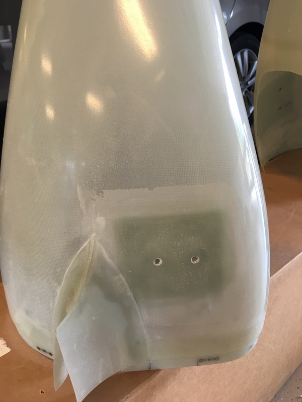
I ground the flox off and added 6-7 layers of 9 oz fiberglass and pressed out the extra resin using peel ply and a roller adding an 1/8" to the wheel pant thickness at the screw locations
Picture
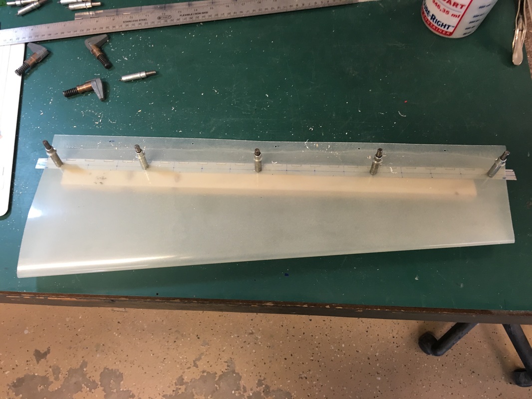
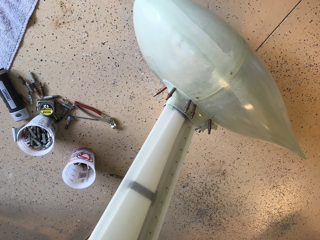
the gear leg fairings with the hinge in place for drilling and riveting.
Picture
Drilling the hinge on a wood block per the plans.
Picture
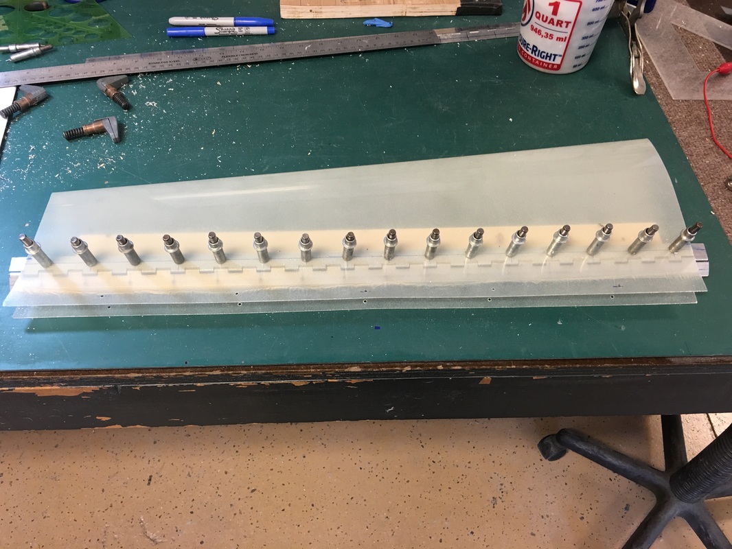
More drilling in preparation for the countersinking and riveting
Picture
Picture
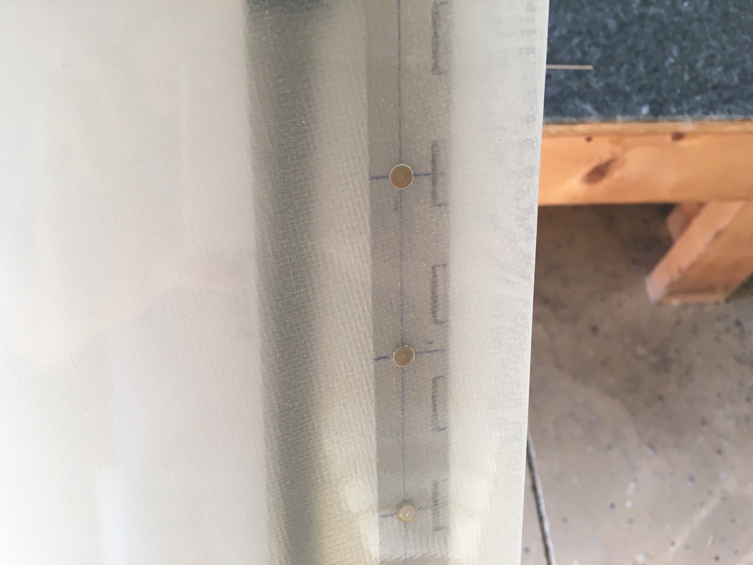
Hinges on the gear leg fairing after countersinking and riveting
Picture
Picture
Picture
Picture
Picture
Picture
Picture
Picture
Picture
Picture
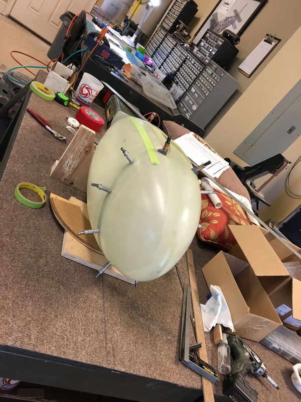
6 layers of glass cloth for the mounting attachment to the brackets. I did this on the RV 7 and he held up very well.
Picture
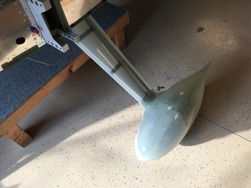
I bonded the wheel cuff to the wheel pants and they are split so you can remove the wheel pants and cuff as a unit. This was also a lifted idea from other builders and my RV 7
Picture
Picture
This is a good shot showing the wheel fairings with the cuffs mounted and the extra layers of glass for mounting.
Picture
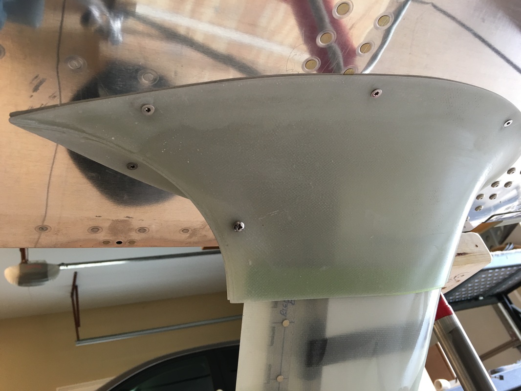
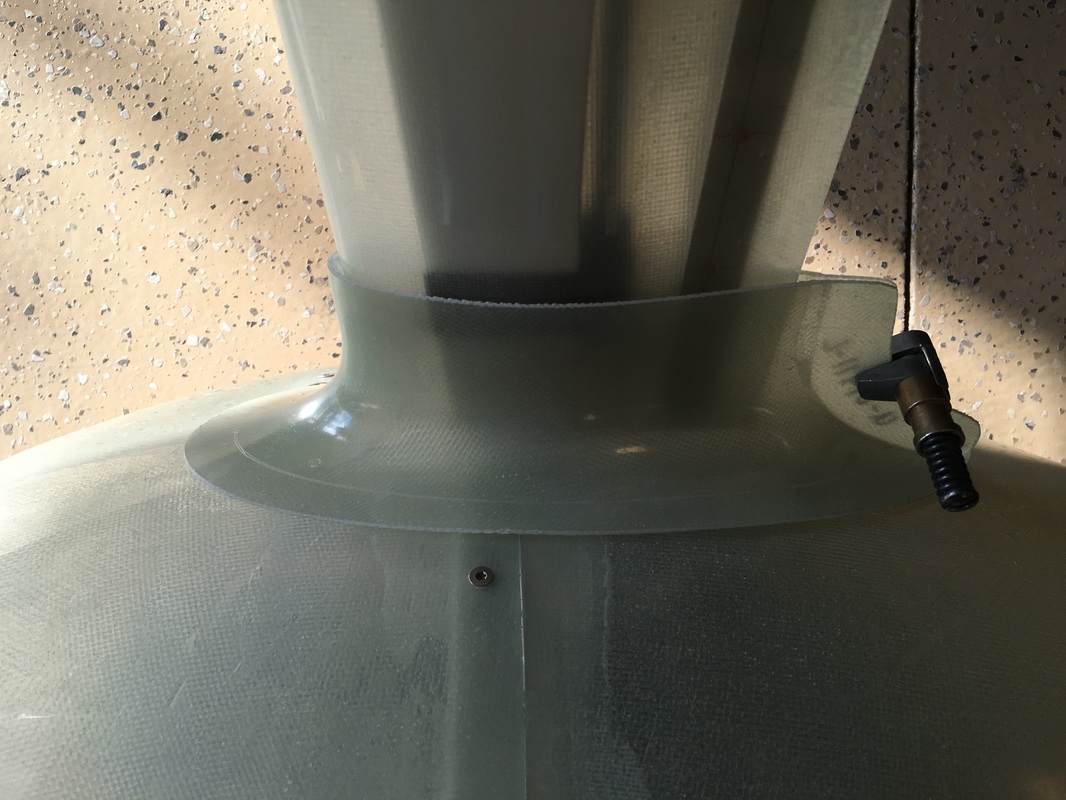
This is the upper main gear strut cuff.
Powered by Create your own unique website with customizable templates.